Ampex MM-1000 Story...

  • Thread starter Thread starter sweetbeats
  • Start date Start date
But.... in your situation, aren't you going to use some of the rack ears in the bottom cab of your MM-1000 for some outboard gear? So the doors would be sorta.... futile to have?

Oh yes-yes. I wasn't bemoaning the fact that some person has them and I don't; rather that I've never actually seen a set in the real world...only in a brochure shot. Other MM-1000 afficiandos also say they've never seen a set. Word has it only the early models shipped with them and most people got rid of them because they were a hassle. The quad video machines from which the MM-1000 was derived had them and it was a more logical arrangement because the gear behind them was more seldomly accessed...like during certain calibration procedures or troubleshooting so it was advantageous to have it covered up. OTOH the 16~24 track MM-1000's (or 8-track systems without the overbridge) obviously demanded pretty constant access to the electronics modules at the very least for meter observation. Plus heat becomes more of an issue with the electronics there I'm told as opposed to what would be there on a quad machine...there were more fan units I believe actually mounted in the racks whereas the MM-1000 just has two fans in the floor of the console. Depending on how things go when it is setup as a 16-track, I may change the cooling array. The stock cooling setup doesn't really make a lot of sense.

I DO have 10U worth of gear mounted in there right now in addition to the stock Ampex stuff, and eventually there will be 8 electronics modules down there anyway.
 
A reel head-scratcher...

Look back at this post...

So I had received that NOS Ampex quad video deck erase block from which I scavenged the 2" rolling guides, right? And I was disappointed to find that one of the guide assemblies had a partially siezed bearing in it, right? Well, I was consolidating some stuff tonight and pulled those out, and they both are smooth as grease on butter. Huh! They've done nothing but sat. I don't get it. But both are now totally operable. And MAN I'd forgotten how smooth they are. They are inarguable the smoothest tightest tolerance rolling thing from a tape deck I've ever felt...incredible.
 
Haven't done much on the MM-1000 but I am in process of procuring the last bits I need for 16-track conversion.

As I've mentioned a couple times the MM-1000 has been in our new garage since later in the Summer during construction. Its been wrapped up in a sheet and plastic...still getting dust in at stuff as the garage has been a construction zone, but its stayed pretty clean except for the cats that come in a pee on stuff. And then of course now that things are good and wet here with the rainy season the garage has become somewhat humid. I didn't realize just how humid until the other day when it went from upper 30's low 40's to around 60...and very quickly. So the concrete floor, which is well sealed, was still very cold and we've been parking one of our vehicles regularly in there which comes in all wet...anyway my point is that the floor and everything close to it had water droplets beaded up all over it, including the MM-1000...and I noticed clips and clamps that were holding the covers on the MM-1000 were rusting. So I got it inside. There's no carpet on the floor of the studio yet and I was waiting until that was installed to move Matilda in but (duh) its on wheels so I'll just roll it out and roll it back in when its time for carpet. Had to get it in.

Powered it up and ran the transport functions for the first time since late spring. Runs healthy BUT the problem with PLAY working intermittently is still there (even after the control box recap) and now there's a new problem...channels 1, 3, 5, and 7 won't go into record. Those 4 channels are powered by one supply and the record control voltage passes through from the control box. I imagine it will be relatively easy to track this down and who knows...maybe I'll find the PLAY issue too as I'm suspecting a relay issue, either its not getting holding voltage or something else.

Anway, all to be expected AFAIC with a 40 year old machine that's been sitting.

Here it is sitting about where it will sit permanently in the new studio:

IMG_0083_1_1.JPG
 
Yup!

A cold damp garage ain't no proper home for an old soldier! :(

Glad you moved it to a better spot and hope you get to the bottom of the issues you mentioned!

Cheers! :)
 
Turns out the issue with record-arming channels 1, 3, 5 and 7 is just a futzy connection at the power supply input for those channels. I messed around with swapping the inputs to the two supplies. I can make the problem happen by manipulating the input connector to the applicable power supply. The contacts all look really good so I need to either bend the female cinch jones contact for the +24V record relay power or the common to get better contact (if that is the issue), or it could just be a bad wire or a cold solder joint. It is working for now so I'll leave unless it gets problematic later. Then I'll dig deeper.

Getting ready to solder the input/output snake back up to the I/O panel. Good gracious...the braided shield in that cabling is the most tightly woven densely packed braided shield I've experienced in cabling of that size. I typically strip the outer sheathing and then unbraid that section and twist to connect to pin 1...this will take some time. And the center conductors are tightly twisted...gooood quality stuff.

Still dunno about the PLAY issue...have to study the schematics...its funny...it was doing its thing the other night where I can hit PLAY and you can hear the relay clicking but the rest of the works won't kick in (pinch roller namely...)...so I'd hit PLAY a bunch of times and it didn't work and then I went to do something else just letting the machine sit idle but powered and all of the sudden *chunk* it fully engaged into PLAY mode. I don't feel like the machine has an attitude. I think it wants to work, there's just something making it hard to do, and I'll find it.
 
Turn it on and leave it on for a day or two or more. It needs to get warm and burn all the moisture out of the system. Coils, caps, contacts, windings, etc are all affected by cold and damp. let it get, well, hot.
 
Hey thanks for that suggestion. Never thought of that.

So you mean like in PLAY or even REC mode (without tape loaded naturally) so that both reel motors are spinning and relays are charged? That sort of thing?
 
I haven't been running the Ampex non-stop but I have been running it for extended periods over the last couple days. When is dark outside the lamps cast a red glow into the utility room just outside the sound room. Here's a pic of what you see as you come around the corner early in the AM:

IMG_0021.JPG


And this is neat...this is looing down the backside of the control panel...nice glow:

IMG_0024.JPG


Still no real progress on the PLAY issue but I've noticed a couple other clues that will help to narrow the culprit down when I get to pulling the schematics out and hunting it down.
 
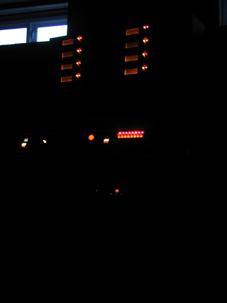
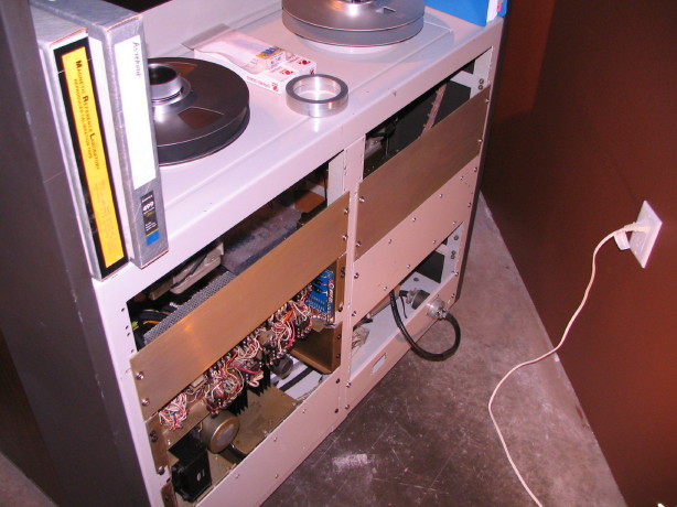
So I've been taking Technoplayer's suggestion and turning the machine on for hours at a time and just letting it run and you know what? The PLAY issue as well as the record arming issue for tracks 1, 3, 5 and 7 seems much improved. This is part of what I like about big old discrete electronics. Sometimes just working them works the bugs out. Not always the case of course, and naturally there are plenty of other pitfalls to "big old discrete electronics", but the MM-1000 does indeed seem to want to work.

Doing a little back-tracking with bearings.

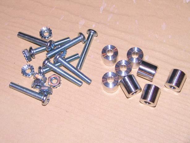
There are several places on the MM-1000 that use "608" ball bearings. These are common "skateboard" or "inline skate" bearings with an 8mm ID, 22mm OD and 7mm thickness. I've been getting my bearings from vxb.com. Prices are good, quality seems very good for the price, and after my recent experience the service has gone from good to fantastic. They ship quick too.

Anyway, I got a pack of the Kit657 from them a year or so ago to rebuild the reel motors in my 440-8, as well as the reel idler roller. One motor has been rebuilt...that's detailed in my 440-8 thread. Super smooth feeling after the rebuild, but granted there's a bit of mass there for damping and inertia, but really nice feeling...far sight better than the completely worn-out bearings that were in there. The reel idler was a vast improvement too but I could feel anomalies in the rotation...just some sort of random mechanical "noise". I figured that was as good as it needed to be and I wasn't going to spend more on more expensive bearings and it was such an improvement, again, over the worn bearings that were in there.

So zoom ahead to the MM-1000. I had 4 of the 8 bearings from that Kit657 left. The MM-1000 in stock trim uses the 608 bearings in 2 places: the reel idler roller (that's the roller with the viscous-damped flywheel), and the pinch roller. As detailed earlier in the thread I've done some rolling guide mods to the 1" tape path including using the "rotary guide" I stole from the parted-out 440-8. The rotary guide uses 608's also. So I rebuild that as well as the reel idler roller with those 4 608's and ordered two more of the same bearings to do the pinch roller. I wasn't happy with how the rotary guide felt...a higher degree of that random mechanical "noise" after mounting the bearings. The reel idler roller and pinch roller were better but still not as nice as I'd imagined. After getting the NOS 2" rolling guides out again and feeling how rediculously smooth those are and after some research I started thinking...the pinch roller is important. It is right there after the playback head. Mechanical "noise" will be present in that section of tape if anything is imparting it and I wanted to minimize that. And the reel idler roller...that is a flutter damping device...an important one on the MM-1000 with so much unsupported tape, and with the viscous-damped flywheel it also reduces wow as well. An important part of the tape path. So again I want to minimize mechanical "noise" and in effect enable the assembly to do its job to the best of its abilities/design.

I contacted VXB to discuss my predicament...didn't want to spend $100 on a full-compliment full-ceramic bearing you know? Figured there HAD to be something of a happy medium on performance and price that would be at least as good as the stock bearings that came from the factory (which were nice bearings...Ampex was picky). The other thing that is important here is that you can't just go get an ABEC-7 bearing and expect it is going to be top notch. The quality control on assembly as well as the quality of the ball cage, ball material, seal or shield construction/mounting...all these things play into the performance of the bearing despite the ABEC rating. PLUS...a bearing designed for high RPM performance is not necessarily suited for low RPM performance. Who cares if the bearing is smooth at high RPM's but "noisy" at low RPM's? You want it smooth at low RPM's during PLAY modes. After batting terminology around and getting them to understand what I really needed and why I wasn't happy with the Kit657 bearings in certain applications they sent me up their "best 608's" to sample...I got them. They're the Kit7809. Now, I figured these can't be the "best" they have...they are ABEC-5 and they are a hybrid (ceramic/steel). So I figure they are the best for my application. Out of the 8 in the package, 2 of them are unacceptable for the detail stuff. The other 6? Nice. If you think it seems wrong that 2 out of 8 aren't great or at least consistent with the others, I've seen it suggested by several that when ordering bearings it is best to order more than you need and hand-pick the best ones. I plan on letting vxb know about the 2 though. At any rate, I figured "okay these are the 'best' for my application" but then I saw the Kit8347 and I though "hmm...those look the same but in an ABEC-7 rating...why didn't they send those?" So I asked and the response I got was this: "...the [Kit7809 bearings] have been made special to the specs that we like..They are an ABEC 5 but they are a non contact seals which is the balls do not touch the seal and the seal does not touch the side of the bearing. Which in return spin faster and longer." And I would assume more smoothly...maybe that's some of the mechanical "noise" I am feeling in the others.

At any rate, here is a video synopsis of this and a presentation of the dynamic differences in the Kit657 and Kit7809 bearings:

YouTube

So the head cover and pinch roller are already back off the machine...you'll understand why after watching the video.
 
Last edited:
I know with cup and cone loose bearing setups if you set the bearing load a bit off it introduces some grit and drag to the feel of the bearing. Perhaps the races on the ABEC-7 bearings were machined poorly? Perhaps they are lubricated with a heavy grease? Otherwise, for a bearing that is rated that highly (I'm no expert) it seems odd that they should be that rough/slow.
 
I think it has to do with the seals and the cages...dunno for sure but what I DO know is that VXB offered to replace the two new ABEC-5 bearings that aren't working smooth, and here are the before/after vids of the pinch roller. With the new bearings it does spin longer but the key difference is that it is tons more smooth...

BEFORE
YouTube

AFTER
YouTube
 
Last edited:
And here's the Rotary Guide after replacing the bearings. I realize after watching the two videos I'm spinning it faster with the new bearings so ignore the amount of time it continues to rotate. The big thing, again, is how much smoothly it rotates...maybe you can hear the difference between the two videos...

BEFORE
YouTube

AFTER
YouTube
 
Last edited:
Hurry up and wait...

Well, I've been dabbling with a number of things on the machine lately...documenting here as a place-holder of sorts:

  1. The PLAY issue, after working the transport more, hasn't improved, so I'm going to need to just dig in and figure it out.
  2. I've been doing some initial tests of how well the headblock is setup, "painting" the wear surface of the heads with a Sharpie and then running tape to see the wear pattern. In doing so I came to the conclusion that the stepped washer I had made to raise the 440-8 rotary guide to the proper height had varied thickness, and the guide overall was sitting too high, kicking the tape to the top of the next guide and then levering it down on the reel idler roller, and the rotary guide wasn't perpendicular. Long story short I killed two birds with one stone and it should work great now though I haven't tested it yet. The other thing is the custom base for the standard rolling guide I installed just ahead of the erase head...same thing...variable thickness. Seems to be mostly at the outer edges of the faces of the part, like the bit got kicked out on the lathe as the velocity increased with the increase in radius while machining...there is a variance of 0.005" which is wayyy too much...that part determines the tilt of the guide which should be nil. I'm talking with my machinist firend to see if this can be rectified. Hurry up and wait for the part to be modified or a new part made.
  3. Something ain't right with the pinch roller...I think it isn't parallel to the capstan shaft...miniscule amount but enough that it *may* be pulling the tape down a little, and I DO know that the pressure is way off...too high, like 5lbs and it should be 2.5~3lbs. That could cause trouble too. I've devised a method by which I'll iron out ensuring that the roller is parallel to the capstan, but the first thing is to set the overall pinch roller pressure. Bummer, I don't have the proper range on either of my homemade spring guages to set that up, so hurry up and wait for the guages I just ordered to arrive. I guess its about time I had a set of real guages since, um, there just *may* be a certain degree of unreliability in my homemade versions. :o
  4. The two additional 39V power supplies are rebuilt, their mounting panel has been cleaned and polished...mount em' up right?? Nope...haven't the hardware yet. Waiting for aluminum spacers to be machined, and having trouble trying to find the proper screws and nuts which are all yellow zinc plated...I'd like them to match but I'm coming up dry finding them so I'll have to go a different route, but first, hurry up and wait for the spacers to arrive.
  5. Back to the heads...Its clear that the IEM 1" heads that came with the machine could stand a lap. This I'm noticing with the Sharpie wear test. The playback head has two wear patterns in it because the previous owner was routing the tape wrong, and for quite some time. So trying to set them up when there are two flat spots on one head is, uh, not easy or even fruitless. The other thing is that I've been dialoging with several MM-1000 owners that have had some experience or have some impression of the IEM heads compared to the stock Ampex heads and all of them prefer the Ampex heads. I'm thinking I need to have a headblock with the best heads I have setup right so that it starts off on the right foot...have an email to JRF to price an optical setup and I'd load the guide-modified block with the 440C-8 heads and send it off. Yes, I think I understand how to manipulate the different adjustments, but things are complicated by each head being ajdustable in height, zenith, azimuth and to a limited degree wrap angle and wrap. There are all those adjustments as well as the flutter idler positions...just too much. I'm unsure of myself and it'd be worth having it done professionally. Plus the 440C-8 heads are essentially new (this being the unofficial blessing of John French himself as he has seen these heads) so it wouldn't cost me a relap, just an optical setup. Hurry up and wait 'til I get off my duff and swap the heads and cans out, and until I hear back from JRF.
  6. Prepping to get the I/O snake soldered back up to the refurbished I/O panel. Dragging my feet because it'll be a bit tedious considering the braided shield is so dense and tightly wrapped. Hurry up and wait for me to do it.
What I do know is that the transport sounds cool when you put it into RWD with the rolling guides all in place...like a hissing that winds up. And the bearing exchanges are lovely. The transport is really precise in action.

What I also know is that my problem with the speed wandering is gone with the 499 compared to the 996. Maybe the 996 was getting a little sticky, and I've had the pinch roller rebuilt since then and tensioned the capstan belt. So that's a relief.

Nervous, but once all that stuff above gets taken care of, it'll be time to put my tape reel where my mouth is, bake the MRL and see how it calibrates.
 
Tedium ad nauseum...

Okay...looking at my last post:

  1. Nothing new on this...thinking of rebuilding the 24V supply first though before anything else as there are only 3 caps and I'd replace the rectifiers as well but that's just 4 diodes.
  2. The custom base for the rolling guide I installed ahead of the erase head that needs rework is now in the hands of my machinist friend...He says he can fix it. I believe him.
  3. Still waiting for the new spring guages...
  4. Still waiting for the additional parts to come back from the machine shop, and I still need to get hardware.
  5. Heard back from John French...$150 for an optical setup on the block. He remembers the heads. Concurs that they shouldn't need a lap but we'll have to confirm when he sees them. $150 honestly seems like a penance for the insurance of the proper setup. I got the heads, head cans and other parts swapped out. As soon as the part being reworked (detailed in item #2 above) comes back I'll be able to send the block off to JFR. Here is the block waiting for its travel ticket:

    IMG_0634_3_1.JPG

  6. Got the channel 1~8 I/O snake prepped for soldering back up to the jack panel. Anxious to have this one behind me. I figure I've got at least 7 man-hours into that I/O panel. It looks great and I don't believe I'll ever have to worry about a flaky connection there but...ugh...the braiding on the shield in that wire...takes like 4 minutes just to get the wire unbraided over a 3/4" section to have it ready to solder up to pin 1. Here's a shot of the braiding, and an overall shot of the task site:

    IMG_0631_1_1.JPG


    IMG_0633_2_1.JPG


That's all for now!
 
Last edited:
At least digital and analog both agree on one thing - it's best to do math in powers of 2.
 
The I/O snake for channels 1~8 is ready to solder up. Now I just have to, uh, solder it.

IMG_0737_6_1.JPG


I also got the spring guages so I can properly setup the pinch roller.

Okay...little side foray here. I received some information on an affordable alternative for the meter lamps on the electronics modules. The stock lamps are very hard to find and are around 7 bucks or so a piece. They aren't very hearty eiter so it is pretty common for lamps to be out. All the meter lamps work on the 8 channels loaded in the MM-1000, but I think only 3 work on the other set of 8 channels I took out of the 440-8 I used to have. So I took one of those extra modules and opened it up to gather some ideas for how the lamps could mount and wire up and such...While I'm in there I think I'm going to clean the module up and replace/upgrade some parts so that it is ready to A/B test with the fully stock modules that are presently loaded. Here is the module...a little beat up and the top cover won't fit on right (card cage needs to be repositioned), but otherwise straight-forward..."safe" and "record" lamps have been replaced with LED's:

IMG_0732_1_1.JPG


IMG_0733_2_1.JPG


The three main things I'm going to do in the module are to bypass C23, a 4uF input coupling cap that is only necessary if using the mic preamp plug-in transformer module, replace the output coupling cap C15 with a 470uF/50V FG series Nichicon MUSE cap (stock is 250uF), and replace C34 on the capacitor bracket...C34 is part of the power supply for the module...I believe it is a secondary filter cap...I'm replacing the stock 1500uF/40V with a Nichicon PW 1500uF/50V. The other large can caps are multi-section and aren't in the audio path so I'm going to wait and see how things work before delving into that...that will potentially involve vector board like Steve Puntolillo had John Chester do on his MM-1000, because those two cans house 7 caps total. Anyway...

Here is C23 just behind the octal socket:

IMG_0736_5_1.JPG


Here is C15 behind the card-cage:

IMG_0734_3_1.JPG


And here is C34 on the cap bracket:

IMG_0735_4_1.JPG


Anyway, stay tuned!
 
Some additional info to the last post...

Here are the spring gauges...I'm very happy with them. They were $40 for the two of them shipped. GCalo found the place, Sciencelab.com. Anway, they'll be a far sight less kludgey than my homemade ones...sometimes, many times, it pays to just get the proper tool:

IMG_0742_1_1.JPG


And the lamps for the meters...GE 24X slide-base switchboard lamps. NOS pack of 10 in original packaging. Neat. They'll require modding to make them work but sources say they'll last a long time:

IMG_0744_2_1.JPG


IMG_0745_3_1.JPG


Finally got all the hardware to mount the power supplies for the channel 9~16 electronics to their panel. I looked high and low for yellow-zinc plated keps nuts and screws but no small quantities to be found so I had to go with standard zinc plated...then there are the aluminum spacers to the right my machinist friend made:

IMG_0747_4_1.JPG


And here they are mounted to the panel:

IMG_0751_7_1.JPG


And last but not least mounted up to the machine...maybe overkill racking them up in the machine since there is, as of yet, no harnessing or anything for them to power, but I figured what better place to keep them rebuilt/upgraded vintage PSU's safe than racked up in the spot where they belong...its the one on the middle right. The open spaces on the lower right are for the I/O panels...the open spaces on the top right and left are for warm air to exit:

IMG_0754_8_1.JPG


And I also got the rolling guide part back from my friend...the one that had thickness inconsistencies...at first I thought he'd just reworked it which is all I expected and asked for...nope...he made a whole new part, and its exquisite. My index finger is pointing to it in the picture. The headblock assembly is now ready to send off to JFR for a complete optical setup.

IMG_0749_6_1.JPG
 
Things are starting to look really good.
Love the headblock.Great job.
Cant wait to see the finished product.
 
Back
Top