Ampex MM-1000 Story...

  • Thread starter Thread starter sweetbeats
  • Start date Start date
Looking nice Cory, looking very nice!!!

The VU bulbs look interesting. I'd thought about modding our MCI machine for LED meter lights as some others have done, but probably not worth the bother considering it uses off the shelf bulbs that cost less than a buck apiece. Had you looking to LEDs for the Ampex?

I got my Ohaus transport scales off ebay for about 8 bucks a pop...yours look like they may be a bit nicer though!
 
Had you looking to LEDs for the Ampex?

Call me nutty but LED's don't glow right for analog VU's IMO...they look too "digital"...the way the light oscillates...nawp...gotta be incandescents for me.
 
The strobe-light type pulsating behavior of LEDs is nerve-racking to me. I hear ya.
 
Call me nutty but LED's don't glow right for analog VU's IMO...they look too "digital"...the way the light oscillates...nawp...gotta be incandescents for me.

You TRULY are an analog guy, Cory :D Makes sense...and pardon my grammar in that post. Egads!
 
I was all set to send the 1" headblock off to John French and I figured I had to do something first...The scrape flutter idlers were nice and smooth and everything, but I started thinking like I always do and not knowing when they were last cleaned and lubricated I decided to pull them and take them to the local jeweler like I did the parts for the 2" idler. You see the thing is that setting those idlers is critical to the setup of the block...their position effects the wrap angle on the heads and the way the idlers mount on these machines you can't set it, remove it and reinstall in the same position, so best to have the idlers tip-top before I send it off and pay to have somebody like John French setup the assembly.

The jeweler did the work in about 20 minutes and charged me $12.50 for both sets of jewels and each roller altogether. Pretty sweet.

Here are the parts back from the jeweler ready to be reinstalled. Notice I labeled each set so it would go back into the proper idler frame AND made note of which jewel was the top and which was the bottom, as well as scribing the radial position...in short, they gotta go back in just as the came out:

IMG_0811_2_1.JPG


These idlers are a little different style than the 2" idler I refurbished. These ones have 'C' shaped pieces at the top and bottom so the idlers also act as guides. I CAN'T get over the precision and beauty of these pieces...the 'C' shaped spacers are precision-ground...like, precision-precision, with these tiny machine screws to hold them in...everything is made from very fine materials and fits together so nicely...lookit:

IMG_0813_3_1.JPG


A shot of the lower jewel installed:

IMG_0815_5_1.JPG


And the first one all back together...pretty-pretty:

IMG_0814_4_1.JPG


Both idlers back together...NO axial or thrust play and yet spin sooooo smooth....I put them back in and did my own coarse setup of the block. NOW its ready for Mr. French.
 
The precision and craftsmanship of these is indeed amazing! <excuse me while I pick up my jaw off the floor> :D
 
The precision and craftsmanship of these is indeed amazing! <excuse me while I pick up my jaw off the floor> :D

It is just gorgeous stuff. Stuff indeed, but for those that like this sort of "stuff" its just nice.

John French should be getting the 1" headblock today to setup so I look forward to hearing from him maybe next week sometime. The communication with him thus far has been outstanding. I expect to be completely satisfied.

The new studio room is almost-almost-almost finished, so pretty soon I'll be rolling the MM-1000 into its permanent spot in there and getting the Soundtracs MX mixer setup and then I can start getting things truly operational.

I still need to finish soldering up the rebuilt I/O panel, and I'm thinking about rebuilding the 24V supply while the machine is still sitting in the middle of the room with the back exposed. There are 3 caps on it and I'll be replacing the rectifier diodes as well so it should be pretty small job. Thinking about doing it because it would be nice to rule out any possible culprits in the supply to the problem I'm having with the machine's hesitancy to enter PLAY mode at times. I'm more of the mind that the problem resides in the relay box, but if I've got the caps and the supply is easily accessed at this point I may as well just do it.

Also, I finally have all the reel spacers needed to run 1" tape using either standard 3-screw reels or precision 6-screw reels with the thicker flanges. You may recall that the machine came with only one of these spacers necessary to mount 1" reels on a machine deisgned natively to run 2" tape...one 1/2" spacer ring below the reel and one on top. Well I had 4 of them made up shortly after I got the machine, but then I was having problems with tape rubbing on the lower flange when I'd run tape spooled on precision reels which are overall thicker than 6-screw reels (by about 0.010"~0.015") PLUS the flanges are thicker by about 0.050". I decided to have a set of spacers made up 0.450" thick so the 6-screw reels could sit a little lower allowing the tape to spool in the center of the reel. But the stack of 0.450" spacer-1" reel-0.500" spacer wasn't thick enough for the fingers on the reel clamper to grab, so I had another set of spacers made up at 0.550". Works like a charm. Here are the sets of spacers:

IMG_0853_1_1.JPG
 
You are maiking me weak in the knees!

I hate when I get encouraged to follow suit!
 
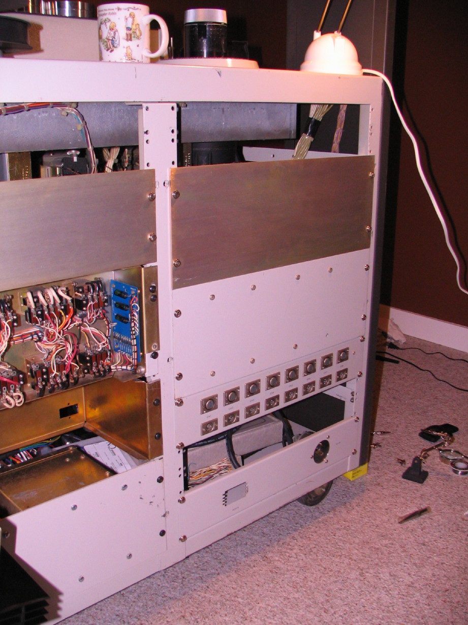
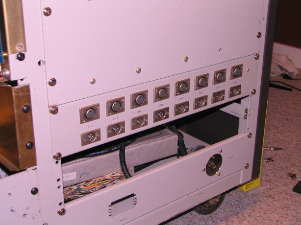
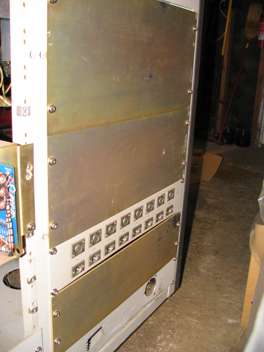
Rebuilding the 24VDC regulated supply. This is the unit that is located 2nd from the bottom on the left rack as you look at the back of the machine. Its sole purpose is to power the 24V devices in the transport. It does not directly power anything in the audio path.

There are 3 electrolytic capacitors (a 22,000uF/50V, 1,000uF/50V and a 50uF/6V). I have a hunch that the 22,000uF cap is fine but I have a replacement Mallory computer-grade cap to put in there that will fit right into the stock clamp. BTW this supply scoped clean when I tested it shortly after getting the MM-1000. The 50uF is probably fine too but I have a Sprague Atom series cap in 50uF/25V flavor so I'll put that in. The 1,000uF cap is the one I'm most interested in replacing as it is of the paper-board type exterior which I'm told are to be treated suspiciously after this many years. Again, I'm not having problems per se with the transport *except* for the intermittent PLAY issue. I'm pretty sure I'll find the problem in the relay box but I figure it doesn't hurt to have the PSU in relatively tip-top shape first anyway. I have a Nichicon PW cap for the 1,000uF cap but I'm shifting course on that...nothing against the Nichicon cap, but I'm going to go ahead and spend the $7~8 to get another of the Mallory computer-grade caps for that one. I believe that will be closer to stock spec and the original cap is a flange-type mount (attaches to the chassis with two screws) and the Mallory cap is the same diameter as the 2,400uF/80V Mallory units I put in the 39VDC regulated supplies and therefore uses the same separately purchased mounting clamp WHICH lines up with the same screw holes. Slick. There is also a diode on the little PCB I'm going to replace. I was also going to replace the rectifier diodes but once I dismounted the component chassis from the frame I noticed what I should have noticed from the schematic...it is a bridge rectifier unit rather than 4 discrete diodes. Well shoot. The schematic lists it as an Electron Devices PB-10 or Motorola MDA 962-2. Had to search for awhile but finally found this cross-reference guide which lists the Motorola MDA 962 series on it. Ahhhhhhhh-HA! 100V/10A. Mouser has some nice Vishay units and frankly its not much if any price difference so I'm going to get a 400V/25A unit. Overkill? Fine. Doing it anyway. So I'll have to wait a bit for the 1,000uF cap and the bridge rectifier to get here but in the meantime enjoy some pictures.

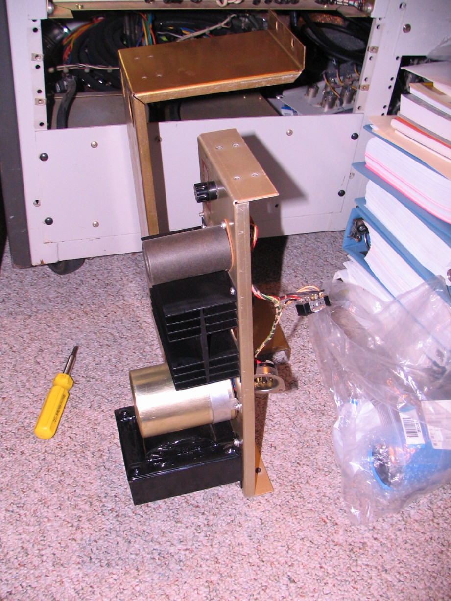
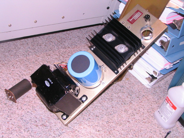
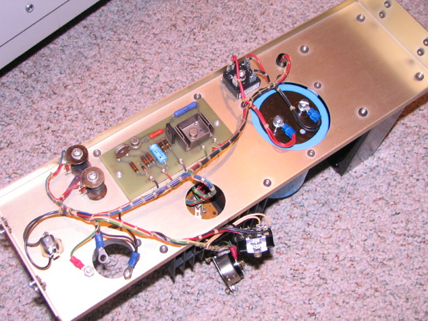
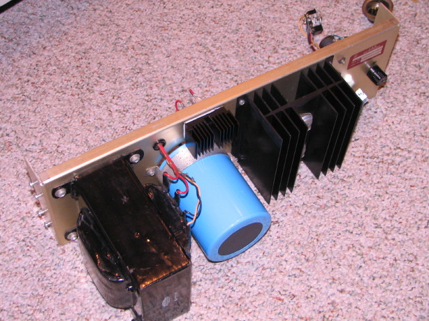
Here is the component frame separated from the mounting chassis...you can see the main transformer at the "bottom" (the big black chunk), then the 22,000uF main filter cap, and the power transistor heatsink above that and then the 1,000uF cap:

IMG_0873_1_1.JPG


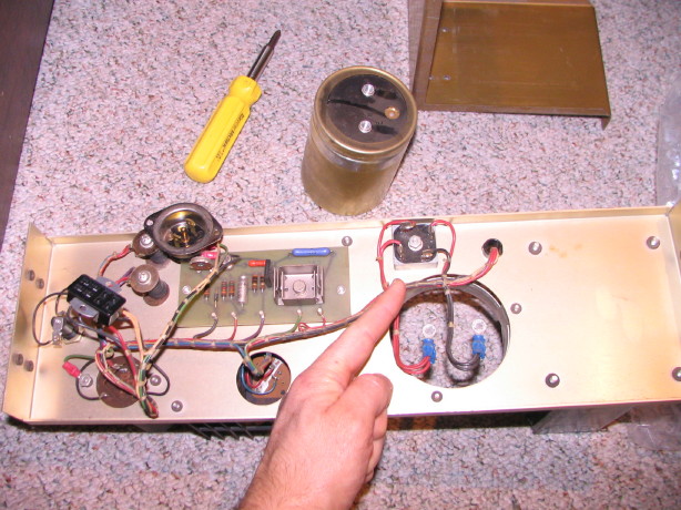
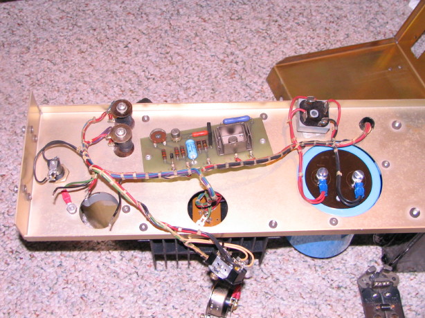
Then here is the "back" of the component frame with the other guts...and my surprise guest Mr. B Ridge Rectifier (located at the end of my index finger):

IMG_0875_1_1.JPG


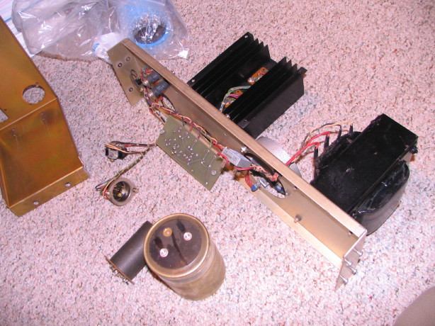
One last shot for now, 22,000uF and 1,000uF caps removed, PCB unmounted to desolder the one diode and the 50uF cap, and rectifier ready to have wires snipped and new one installed (when I get it):

IMG_0878_2_1.JPG
 
10 of the 48 solder joints on the I/O panel are done.

Made some progress on the 24V supply...the 22,000uF cap is in as is the 50uF cap...the diode is desoldered but turns out it is a zener not a rectifier so I've got to get one of those. Cleaned it up a bit...mounted the clamp for the 1,000uF cap (you can see it on the right in the first picture)...found a neat aluminum heatsink for the bridge rectifier (currently isn't one though it mounts to the component frame...lots of steel...probably fine but I'm adding the little heatsink anyway); it'll blend well with the big 'un for the power transistors...

IMG_0909_5_1.JPG


IMG_0910_6_1.JPG
 
Progress...

Finally got the I/O panel soldered up and did redundant testing and all is great.

IMG_0925_1_1.JPG


IMG_0930_3_1.JPG


IMG_0932_2_1.JPG


Doesn't really do it justice but the panel assembly was bent and grimy when I got it and the solder connections were in bad shape...go here to see a pic from early on:
IMG_2542_7_1.JPG


The mounting position for the panel is correct and the 2U space under it is for the channel 9~16 I/O panel which I'm still waiting for along with the complete 16-track harness and some other hardware...among the hardware bits will be a set of the offsetting 6U rack ears so the I/O panels and power/remote connector panel can be inset which gets the connectors out of harms way. Here is a shot of the machine that is donating my parts...you can see the channel 9~16 I/O panel and power/remote connector panel there in the foreground attached to the offsetting rack ears:

MM1000%20parting%20out%202-11.jpg


Also made some progress on the 24V supply...it is all finished except I am waiting for the 1,000uF cap (should be here Tuesday) but the ring connectors for the screw terminals on that cap are installed, the new bridge rectifier and custom heatsink are installed and the zener diode is now installed on the PCB. Literally everything is done except for putting that last cap on which will only take a couple minutes since the clamp is already installed and it is a screw-terminal cap. Couple pics...new bridge rectifier on the upper right and you can see the ring connectors ready for the last cap on the lower left:

IMG_0933_3_1.JPG


This picture shows the little custom heatsink for the bridge rectifier...there was nothing before and that was probably fine but I couldn't resist...looks like a child to the big power transistor heatsink:

IMG_0935_4_1.JPG


Cleaned up some of the channel 1~8 I/O harness...this old wiring gets a sticky coating on it and then years of dust stick to it...nasty. Iso alcohol cleans it up. The pictures don't really show it well but the first is of the back of channels 2, 4, 6 and 8 before they were cleaned (and I'm just talking about the XLR harnessing) and the second shows the harnessing for channels 1, 3, 5, and 7 after cleaning:

IMG_0929_2_1.JPG


IMG_0928_1_1.JPG
 
Last edited:
Yup, dramatic difference between the before and after cleaning / restoration. Real amazing job Cory! :)
 
Thanks, Daniel!

I have the last cap on hand now to complete the 24V supply rebuild.

The harnessing and other parts to complete the items needed for 2" conversion are on the way!

John French got back to me on the 1" headblock...heads are good, 0.002" of wear but there is a flat spot so it isn't possible to ensure the wrap angle is spot on. I'm into it $150 already. For another $300 +/- he can lap the heads, they'll be at 90%, he can guarantee perfection on the wrap angle and they are set for life. What would you do??
 
I would fully pack the entire unit and all the parts and promptly ship it down to me today!!!

Well uh...that's...uh...not exactly the kind of advice I was looking for... :D
 
Boy Cory, it sounds like a chunk, but it sounds like for under 500 you'd have a known good headstack for life!

I'm not gonna lie, I'd have busted out the spool of Belden, some fresh zip ties and made new i/o wiring harnesses though...but then I have a low "gooeygrime" tolerance :D
 
Heheheh! :D

"Busted out the spool of Belden" :)

Yeah, I know...I hear ya. I'm seriously burned on making up cables though and I've got so many more to do to interface the mixer with the tape machine...and the other thing is that the cable on the Ampex is seriusly some of the best quality cable I've ever worked with. Granted there's no foil shield, but the quaility of the stranding and the density of the braided shield as well as the quality of the jacketing...its worth cleaning it up. I really want to be done with this machine or at least be at the point where its in use...20 minutes with a rag and some iso alcohol is a whole lot faster and cheaper than making up new harnessing especially when the existing wire and hardware is "the good stuff".

And with the headblock I'm thinking I'm going to go without the lap. 0.002" is a small wear depth especially on new heads...reinforces these heads were only used on a couple projects and I trust that Ampex setup the heads properly in the 440C-8 they came out of when it left the factory so I think its safe to assume that the wear pattern is centered in the gap. I can use a marker and a 10k tone on my MRL to tweak the wrap if needed...head height (as well as the other components in the path like the guides and idlers) and zenith are THE bugaboos and then azimuth and then wrap and JRF will take care of the heights and zenith along with azimuth and wrap and I can do those minor tweaks on the latter two if needed.

Plus with this work that JRF IS doing I'll have a full head report and he's looked at the heads under high power magnification and I've talked with him about what he saw and they look good, so I STILL have information to make the assemply "known good".

And I don't have another $300, so, yeah.
 
Cory, well, at least with JRF you're indeed getting exactly what you're paying for, no surprises, head stack which is fully lapped (to new spec), 90% life remaining (that's a lifetime), full paper report and all the proper adjustments. It would be nice if we had the same sureness about those "NOS heads" but we still don't... At the same time if you pass on the JRF deal and the other "NOS" ones don't happen or are not as stated then ....... well, you know.. more time and money lost. If there is only one $300 dollars to spend now and you want it done, I'd go with the sure thing and not look back. No need to look at anything else, IMHO.
 
Cory, well, at least with JRF you're indeed getting exactly what you're paying for, no surprises, head stack which is fully lapped (to new spec), 90% life remaining (that's a lifetime), full paper report and all the proper adjustments. It would be nice if we had the same sureness about those "NOS heads" but we still don't... At the same time if you pass on the JRF deal and the other "NOS" ones don't happen or are not as stated then ....... well, you know.. more time and money lost. If there is only one $300 dollars to spend now and you want it done, I'd go with the sure thing and not look back. No need to look at anything else, IMHO.

Good points for sure...the one thing to add though is that it isn't $300 total, it is $300 MORE than what I'm into it for anyway which is $150...so $450 total.

I'd do it if I thought there was that much to gain or if the wear pattern was off on the heads, but that's not the case. Those heads were run for two projects and that's it...Ampex set them right when it came out of the factory so the 0.002" deep wear pattern is centered on the gap, centered between the heads with correct zenith and azimuth. John French has lined up the zenith, height and azimuth and he can't guarantee perfect wrap angle even on new heads...understand I'm talking about JRF "perfect" here...point is that the wear pattern just makes it a little more sketchy to set the wrap angle and you are relying on the previous adjustment to be correct in order to continue a correct wear pattern. I trust Ampex did it right, John French will get it as close as he can and I can always check with a marker and the 10k tone on an MRL if I think I can do better. :rolleyes:
 
Back
Top