Ampex MM-1000 Story...

  • Thread starter Thread starter sweetbeats
  • Start date Start date
Rough day...I need help.

Rough day as far as progress on the MM-1000.

I got the last cap installed in the 24V supply last night, and then today powered it up to see how things looked.

Still not really sure what happened or how it happened, but I got an arc, and it now seems that the output from the rectifier is messy.

I'm not trusting my scope either (and/or my abilities to be using it right).

I kept the output cable from the supply unplugged so the supply was isolated and had the supply sitting on the floor outside of the MM-1000 console.

So here's what happened:

I powered up the Ampex and then took my Fluke DMM and measured the output at the output connector. I was getting 19VAC. I later realized that I had forgotten that the output connector not only carries the regulated 24VDC power but also 120VAC pass-through...not sure what pins I had the DMM on so I guess that bit is not very useful.

Anyway, confused I turned on the scope and went to put the ground lead of my probe on what I thought was one of the 24VDC ground reference pins and *ZSSHNNNAP!*

The breaker on the Ampex kicked off quick. Fuse still good in the 24VDC supply.

The little metal pin I had clipped in the ground lead was all melty...lotsa black on the clip. The breaker kicking over saved the pin from being welded to the connector in the output socket.

What I do know: the 24VDC PSU output pin to which I touched the ground lead on the scope probe was actually the hot leg of the 120VAC pass-through.

I also know I was stupid not to have the 24VDC supply chassis grounded. It gets grounded when mounted in the console but as I mentioned I had it sitting on the floor.

For subsequent testing I had 12AWG solid copper wire coupling the PSU chassis to the MM-1000 console.

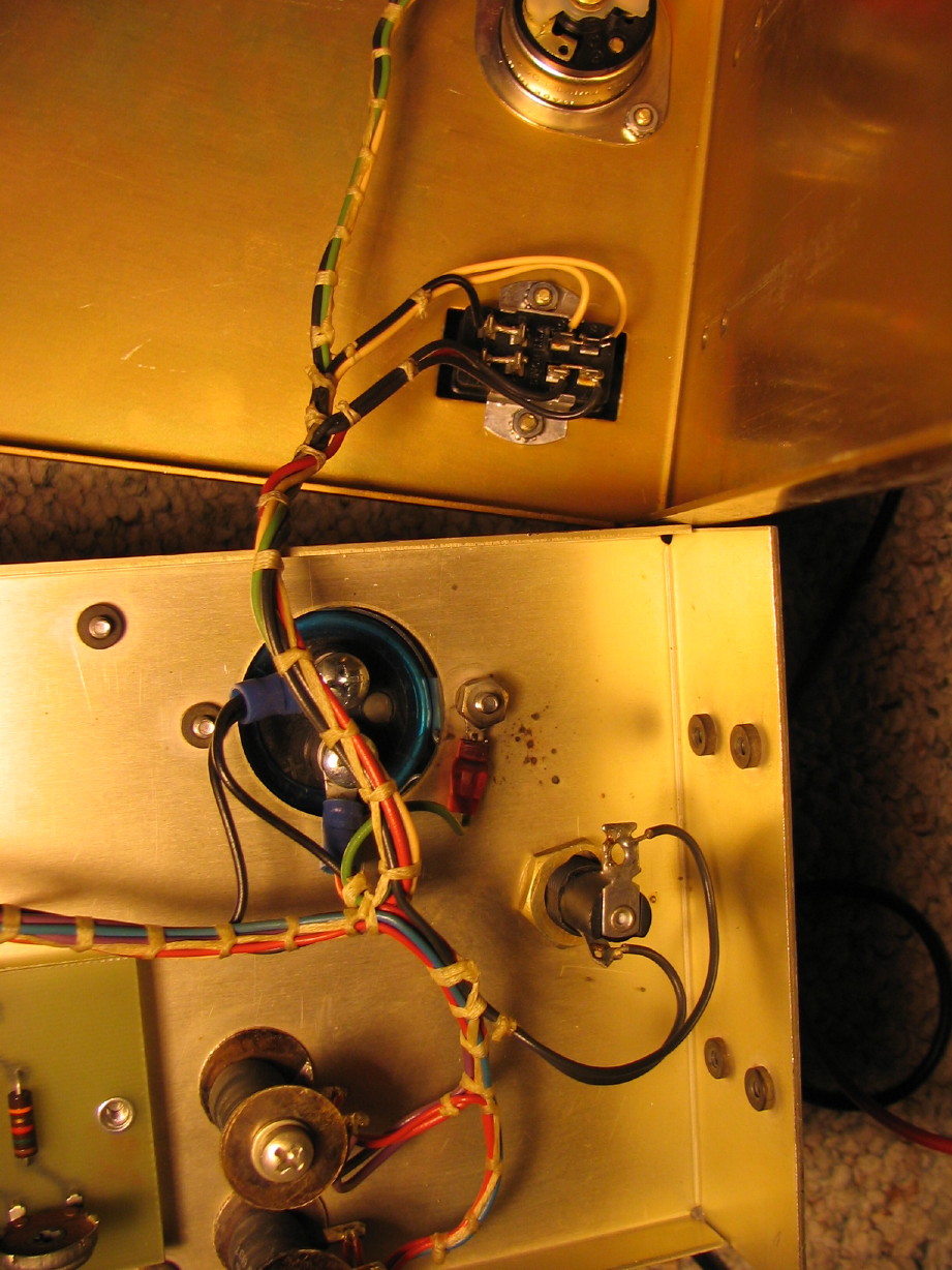
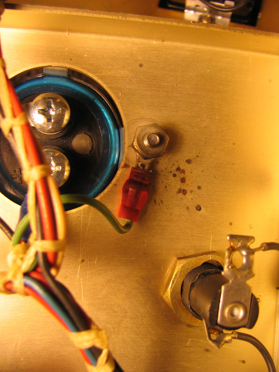
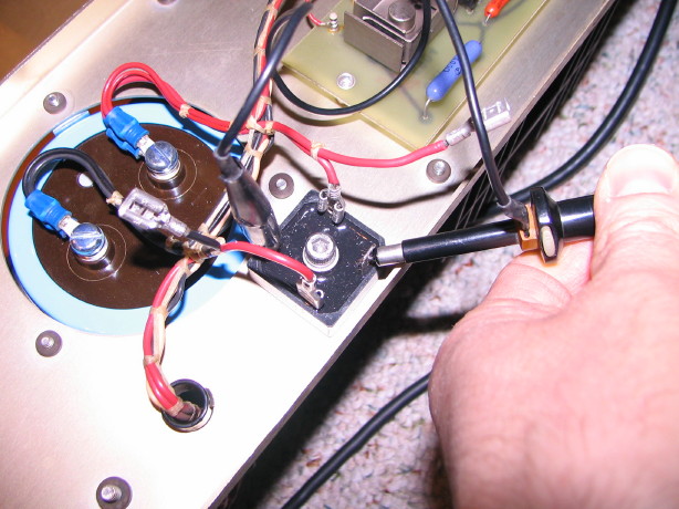
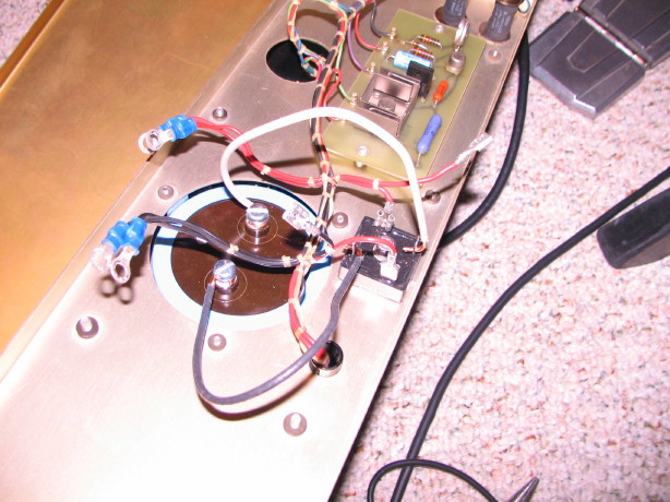
So the ground clip took a hit but when I opened the PSU chassis up I saw what also happened inside...that 120VAC hot leg arced to the ground lug inside as well as the chassis frame close to the ground lug.

Here is the ground lug...you can see the blackened crimp ring on the ground terminal and the black spots on the chassis close to the ground lug:

IMG_1020_1_1.JPG


IMG_1021_2_1.JPG


So I'm just lost as to what caused this to happen...can anybody help me with that?

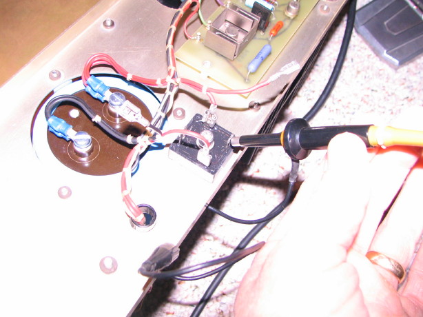
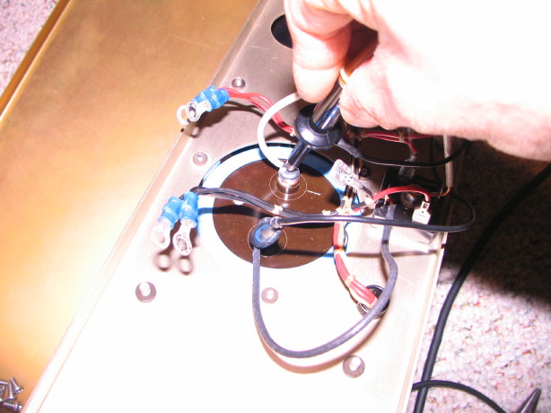
After properly grounding the PSU chassis I disconnected the output of the main transformer at the rectifier and measured 28~29VAC which is normal. I then connected the transformer output to the rectifier and disconnected the output terminals of the rectifier (to keep it isolated) and I've got all kinds of whacky AC and DC wave forms...its a mess. Its a 400V rectifier so I just don't understand why it would be shot but I think it is.

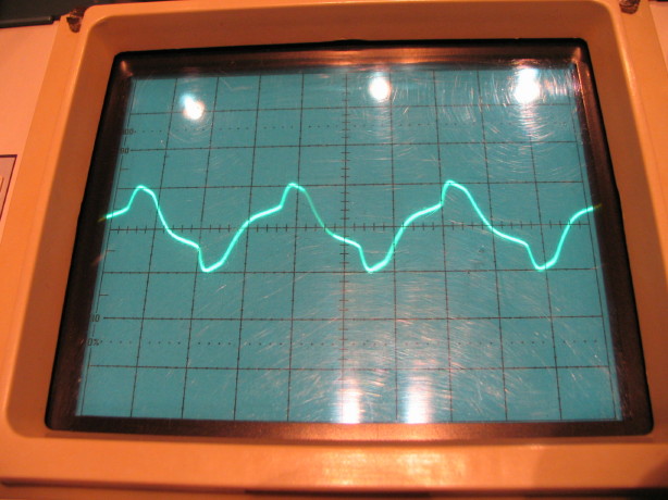
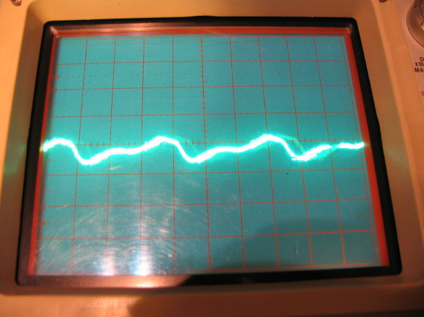
Here is the AC waveform at 5ms TIME/DIV and 10 VOLTS/DIV (and understand that there shouldn't be any AC voltage at the output of the rectifier):

IMG_1023_1_1.JPG


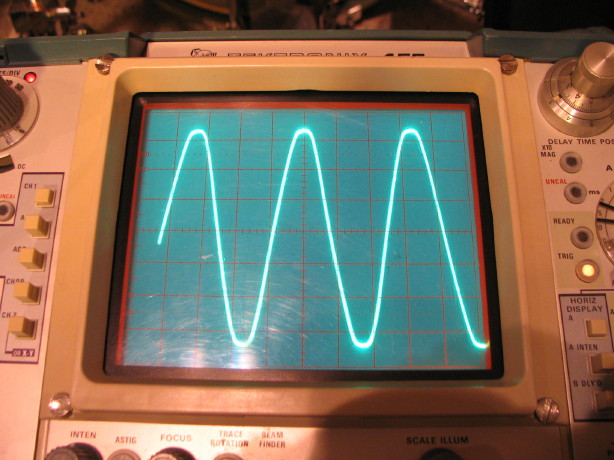
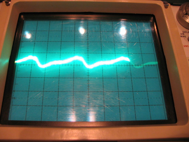
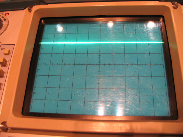
And here is the DC waveform also at 5ms TIME/DIV and 10 VOLTS/DIV (and the "waveform" should be a flat line at about 2.4 divisions off of the origin on the Y axis):

IMG_1024_2_1.JPG


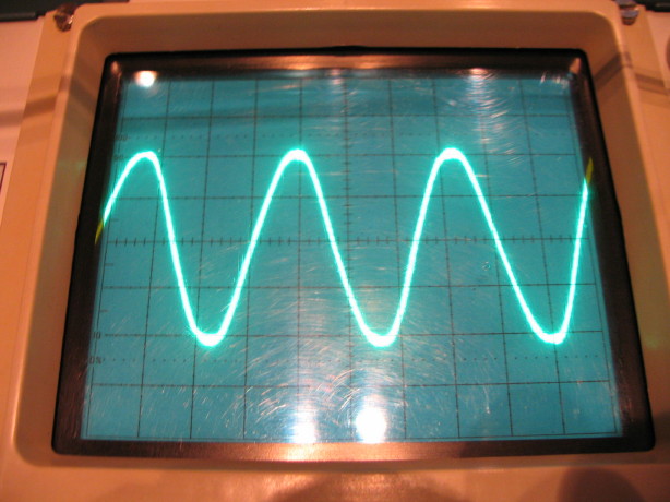
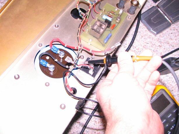
But here is another thing that's making me nervous...I'm wondering if something isn't wrong with my scope now. Here is what the AC waveform looks like straight off the mains power at 5ms TIME/DIV and 50 VOLTS/DIV...if I'm reading that right that is over 300VAC but I know its not because my Fluke meter and the LED voltmeter on my power distribution unit both say 118:

IMG_1027_3_1.JPG


I know this is asking a lot but can anybody help or at least ask questions that will trigger more thinking about this? I need to know what happened and whether or not the rectifier is toast and my brain is slow ATM.
Oh, also, here is the schematic for the 24VDC supply...
 
Good points for sure...the one thing to add though is that it isn't $300 total, it is $300 MORE than what I'm into it for anyway which is $150...so $450 total.

I'd do it if I thought there was that much to gain or if the wear pattern was off on the heads, but that's not the case. Those heads were run for two projects and that's it...Ampex set them right when it came out of the factory so the 0.002" deep wear pattern is centered on the gap, centered between the heads with correct zenith and azimuth. John French has lined up the zenith, height and azimuth and he can't guarantee perfect wrap angle even on new heads...understand I'm talking about JRF "perfect" here...point is that the wear pattern just makes it a little more sketchy to set the wrap angle and you are relying on the previous adjustment to be correct in order to continue a correct wear pattern. I trust Ampex did it right, John French will get it as close as he can and I can always check with a marker and the 10k tone on an MRL if I think I can do better.

Ah, I see... Well, in that case, if it was me, I'd probably pass on the lap. I mean, very, very low use and even wear on those heads so why bother? I'd probably just make sure to align 'em right and keep the $300. I would still have 90% life left on even worn heads, without spending an extra dime. Yeah, in fact, the more I think about it, based on John's assessment, I would pass on the lap and save my money. I think that the even, centered wear is the key here. Not to say % wear is not but, being a bit more permissive here, I think we're looking at close to new heads here, just 10% even ware. That's nothing and no reason to spend the extra money on a lap, IMHO.
 
Last edited:
Sorry, Cory, wish I could help with your MM-1000 issue. I hope someone chimes in soon.
 
Thanks, Daniel...me too.

The other question I have is regarding the output of he main transformer:
When I set my meter to AC volts and connect the probes to the two output wires on the main transformer it is 28~29VAC which is expected. However when I put one probe to the chassis ground and the other to each output wire (one after the other) I get about 16VAC on one output wire and about 9VAC one the other...is this normal? I expected them to be the same and I'm wondering if the rectifier doesn't deal well with that or something...
 
I have to think about it a bit, but that DC waveform looks like a half wave rectified AC waveform. Is this after the filter cap?
 
Thanks for your willingness to think about it. :)

No it is before the filter cap. I put the ground clamp on the negative output of the recitifer and touched the probe to the positive output and the filter cap and everything else downstream was disconnected...just 120VAC to transformer, transformer output to rectifier, rectifier output monitored via scope.
 
Ok, so if the DC waveform you ae showing is at the output of the bridge rectifier, it should look like the bottom picture below....which it does, right?

All the bridge is doing is inverting the lower half (negative swing) of the AC. To get flat line DC you need the post bridge filter cap.

You are correct that there still shouldnt be AC coming thru the bridge.

What does it look like AFTER the cap?
 

Attachments

  • waveform.webp
    waveform.webp
    30.7 KB · Views: 138
Well, I did some more testing to confirm what I was seeing and to see if I could replicate your waveform examples. Nothing matches up exactly...I'm going to just put a bunch of pictures below with corresponding settings and hopefully that can help make correlations.

BOTTOM LINE: it looks like the power is clean post filter cap (no AC voltage to speak of and DC waveform is flat). So maybe the rectifier is okay. Doesn't make me any less freaked to connect the rest of the regulator circuitry...or answer why I got my own little lightening storm when I touched the ground lead of the scope probe to the 120VAC hot leg output...

When the scope is DC coupled and set to 5ms TIME/DIV and 10 VOLTS/DIV, and the ground lead and probe tip are like this (ground lead to rectifier "-" output and probe tip to rectifier "+" output)...

IMG_1041_1_1.JPG


The scope displays this:

IMG_1042_2_1.JPG


If I keep the same settings on the scope and move the ground lead to the chassis and keep the probe tip on the "+" output like this...

IMG_1044_3_1.JPG


The scope displays this:

IMG_1045_4_1.JPG


Then if I move the probe tip to the "-" output (all other settings the same) like this...

IMG_1046_5_1.JPG


The scope displays this:

IMG_1047_6_1.JPG


Just for fun, when I put my DMM leads on the +/- rectifier outputs and measure for AC I get this:

IMG_1050_9_1.JPG


So there is 1.6VAC getting past the rectifier... :( :confused:

Now when I connect the filter cap to the rectifier output (with the rest of the system disconnected) like this...

IMG_1051_10_1.JPG


And connect up my scope probe to the capacitor terminals like this (ground lead to "-" terminal of cap and probe tip to "+" terminal)...

IMG_1052_11_1.JPG


The DC coupled scope display looks like this (still 5ms TIME/DIV and 10 VOLTS/DIV...yes the output of the rectifier is about 39VDC):

IMG_1053_12_1.JPG


Couple the scope to AC and the display looks like this (with the VOLTS/DIV set to 50mV):

IMG_1055_14_1.JPG


So...that's...good...right?? I think the last picture is just displaying environmental noise because my DMM set to AC volts rapidly pulls to 0.2mV when I put the meter probes to the +/- terminals of the filter cap.

I'm still curious that the waveforms I'm getting at the output of the rectifier don't match the ideals in the diagrams you put up...and I'm still wondering about the transformer outputs not being equal (i.e. one is about 16VAC and the other is about 9VAC...), and of course concerned that there is 1.6VAC getting through the rectifier.
 
Cory,
You are correct that the waveforms dont match. The bottom of the waveform on the alternating half cycles is cutoff early. I am not sure why, but if it were me I would replace the bridge rectifier. That odd half cycle is going to be hard to filter out and may be the cause of the slight AC component you are seeing. If your horizontal scale is the same on all traces ( i presume it is) then the slight "burst" you get in that last display could correspond to that portion of the reticifed waeform where the diodes switch on and off (conduct vs no conduct).
I would surmise the bridge is failing.
 
Thanks, Techno...

New rectifier will be here today...it'll be telling to put it in and scope it with and without the filter cap, but I am really nervous about connecting the rest of the PSU...nothing like shootin' sparks to diminish your enthusiasm for smoke testing... :(

Does ANYBODY know if it is normal that the two output wires from the main transformer are carrying different voltages?
 
How are you measuring the voltage on the output wires? (review Diode bridge - Wikipedia, the free encyclopedia). The output wires are floating with respect to ground (the chassis). The negative bridge rectifier lead is connected to ground I assume and the positive feeds to the caps. The bridge routes the negative portion of the AC waveform (from the respective transformer wire) to ground and the positive to the positive lead of the bridge through one set of diodes on one half the AC waveform then the other set of diodes route the other other lead to ground and so on. These diodes are just a switch whic sent the positive transformer wire at any given instant to the positive bridge rectifier lead and the negative transformenr lead to the negative bridge lead. When the cycle reverses the other 2 diodes take over to do the same. a ground reference is only established by grounding one of the bridge rectifier outputs (plus for a negative supply, negative for a plus supply).

How are you measuring the AC? If you measure referencing to the ground then you are looking at the waveform though the currently activly conduction diode that sends the transformer wire to ground. If the 2 grounding diodes are not matched then you can expect to see a difference. It would not hurt to change out the bridge.


--Ethan
 
Thanks for the reply Ethan. :)

The review from Wikipedia was good...review is always good. I'm pretty comfy with the theory and operation of the bridge rectifier...part of why this is baffling to me. The negative lead of the rectifier goes straight to the negative terminal of filter cap C1, and the positive lead of the bridge goes to the positive terminal of C1. As far as I can tell the 24VDC common floats with reference to the chassis on this PSU. See the pdf of the PSU schematic at the very bottom of post #501.

I just replaced the rectifier with a new part annnnnnd...

EXACT SAME RESULTS! :mad: 
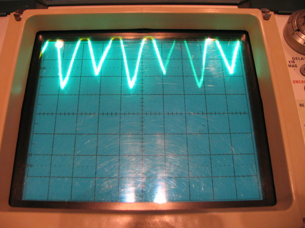
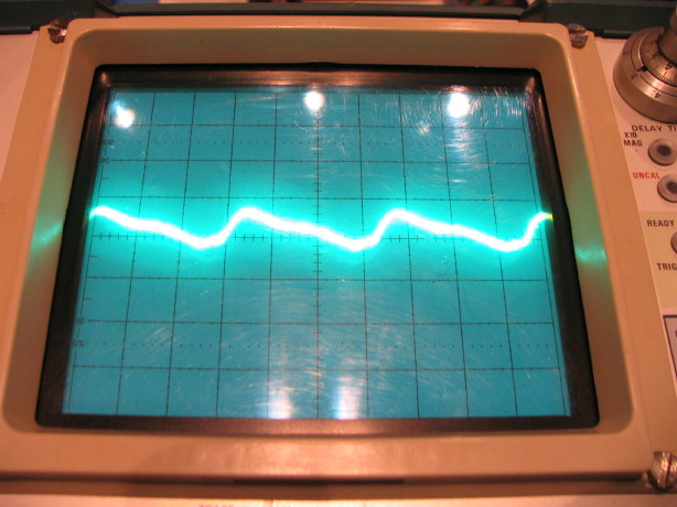
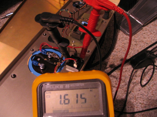
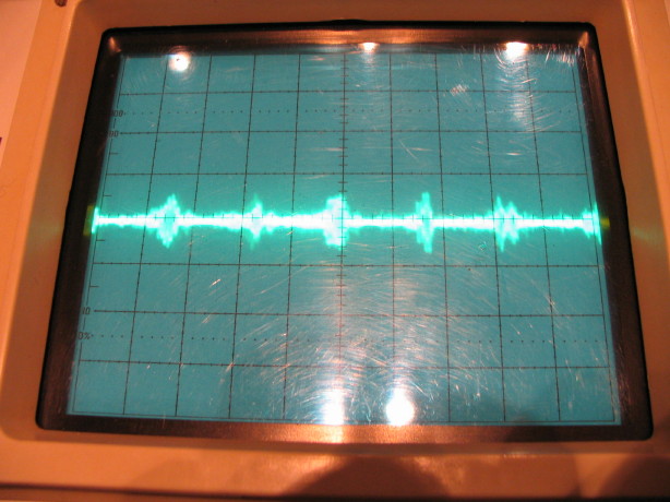
(i.e. the rectifier output DC waveform looks like a bunch of shark's teeth, and there is still about 1.5VAC passing the rectifier...)

What th....

Just to be sure, I took a look at the output waveform of the main transformer (ground clip of scope probe to one output wire of the tranny, the probe tip to the other). Looks good...a little "noisy" but I assume that is normal for a transformer:

IMG_1059_1_1.JPG
 
So many subtle things that can make a big difference...

I'll try to get this right...

Many thanks to evm1024 for taking some time off-list to talk through this with me.

I'm using my scope and DMM wrong.

If you want to follow this explanation it'll help to have the schematic open for the 24VDC supply (linked at the very bottom of post #501).

First of all, the reason for the instigator of this series of posts, the "*ZSSHNNNAP!*", is simple: remember that I forgot that the 8-pin output connector J1 carried a 120VAC pass-through as well as the +24VDC and DC common. When I touched the ground clip of my scope probe to a terminal on J1 I was thinking it was the DC common, but it was the 120VAC hot. The scope is grounded, and I did the same thing as connecting a wire from the ground terminal on a wall outlet to the hot terminal. ZAP!! Dead-short. Dumb. At least I know that the 15A breaker that is the power switch for the MM-1000 works, heheh. It tripped before the household breaker could trip.

So that "incident" isn't indicative of any problem with the power supply.

And the blackened spots on the chassis and ground terminal shown in the first pic of post #501 is very likely just the result of the small but violent spray from my shorted connection on J1.

So then on to my other questions...

The big picture here is that I was thinking of and using the ground clip on my scope probe like the COM lead on a DMM. NOPE! And this mentally capsized hobbyist has now been righted again...The ground clip on the scope probe is nothing more than a safety ground clip. It doesn't have anything to do with measurments, though when used it can clean up waveforms that are displaying environmental "noise" (shunting the noise to ground and separating it from the signal).

And the other thing that is important is that the DC common is floating with reference to the chassis in this power supply...so I'm being equally silly clipping the ground clip of the scope probe to the chassis, OR to the negative output terminal of the bridge rectifier when taking measurements...the chassis isn't a reference, and the ground clip isn't a second probe. This is the same issue with trying to look at the waveform of the output of the main transformer. To measure those things its fine to have a ground clip connected to the chassis (only because the chassis is referenced to the household ground...remember, it is for safety and to shunt noise) but I need to connect my second probe and put channel 1 and channel 2 of the scope into "ADD" mode. and use the two probes to simultaneously measure both output terminals on the transformer or the rectifier. Duh. This makes perfect sense now, and I will take some measurements later, the correct way. :)

The fact that the transformer outputs are different voltages can also be explained using Ohms Law because there is no ground reference at the transformer....there's no center tap, and by measuring across a single transformer output and the chassis there are leakage currents and a very small change in leakage current given the resistance of my DMM can show up as a significant difference in voltage...this depends of course on the gross amplitude of the voltage being measured, but in this case it is obvious because the peak-to-peak voltage at the transformer output is about 40VAC. Bottom line...the fact that I get about 16VAC across one transformer output and the (relatively irrelevent) chassis ground, and about 9VAC across the other transformer output to chassis ground can be reasonably explained to result from leakage currents. The IMPORTANT measurement is the measurement across the two transformer outputs which is about 28~29VAC (according to the DMM set to AC volts)...A-OK, and I'll double-check the waveform later using the proper method on my scope of both channels in ADD mode.

And lastly what about the inconsistent AC and DC waveforms at the output of the rectifier? And what about the existence of 1.5~1.6VAC at the output of the rectifier?

As far as the waveforms, again, I was using the scope wrong. I will check this later as well but I betcha when measured in the proper way the waveforms will look proper, and Ethan said that 1.5~1.6VAC at the output of the rectifier that is rectifying 40VAC peak-to-peak (and with the rectifier output wires "flapping in the breeze") is "great", and that the important thing is how does it look across the filter cap C1 when the rectifier outputs are connected to C1. And that looks fabulous...0.2mVAC, and I think I'm pushing the limits of the meter at that point, so it is really clean. And remember that C1 is only the first filter stage. C4 is the output filter cap. I'll check what it looks like there too.

Ethan also suggested to check the DC voltage differential between the series-pass transistors Q4 and Q5 with some load applied to the +24VDC rail...so COM probe of the DMM connected to the +24VDC output at J1, and the positive probe connected first to the emitter of Q4 and then to the emitter of Q5...they should be similar voltage readings, but, again, leakage currents and variability in the transistors themselves will drive some difference between the two...but this simple test will show that both transistors are functioning okay.

[big deep relieving sigh]

Thanks, Ethan.

This concludes our lesson in do's and don't's with your DMM and scope, and also how to make it appear that there is something tragically wrong with your PSU when (in all likelihood) there ain't a thing wrong with it.

:o
 
That's a good lesson, and one which this novice read with care...glad you got your answer, and cheers to Ethan, lord knows he saved my day on more than one occasion sorting through that MCI transport!
 
Okay, so the bottom line here is that I hooked everything back up and smoke tested it again and all seems fine.

The AC voltage at the primary filter cap (C1) with the rest of the supply disconnected was 0.2mVAC...with the rest of the supply connected that rises to about 4mVAC...still good yes? And the AC ripple at the output filter cap C4 is about 0.3mVAC...very clean if I understand correctly. And I had no problem getting the supply dialed in to 24.00VDC. Very stable.

Next step is to double check the series-pass transisitor differential as Ethan suggested. I'll report on that later.

Still trying to get my head around what I'm seeing on the scope even when channels 1 an 2 are in ADD mode and I'm using both probes to measure things. Like, for instance, here is the waveform I'm getting when DC coupled and measuring across the terminals of C1:

IMG_1074_2_1.JPG


That is anything BUT a nice linear DC waveform (flat line)!

I'm not freaking out about it because I'm getting appropriate readings with my Fluke DMM, but I'd still like to really understand what I'm looking at and why it looks like that and what I'm doing wrong.

Thanks for coming along everybody.
 
Could you be experiencing a prob w/scope? Maybe that's giving the erratic readings.
 
I wondered about that but when I scope the household power it shows a proper sine wave, and the onboard calibrator brings the right results too (300mV square wave).
 
Time to recap it's power supply then!!!

Maybe then check your new circuit with a digital volt meter to make sure it's a steady 115V-117V
 
Anybody interested in seeing pics of the wiring harness out of a 16-track MM-1000 along with some other related hardware?
 
Back
Top