Tascam M-___ Story...

  • Thread starter Thread starter sweetbeats
  • Start date Start date
Holy $hit. You did it, man.

With a little help...no...a lotta help from my friends. :)

In case anybody is interested, here is a video we shot of the smoke test. My kids helped so think of it as a 6+ minute Mr. Rogers moment with the M-___. :p

Enjoy!

YouTube
 
Last edited:
Congrats on turning on the lights. I suspect you feel "power"ful now. ;)
 
With a little help...no...a lotta help from my friends. :)

In case anybody is interested, here's a link to video we shot of the smoke test. My kids helped so think of it as a 6+ minute Mr. Rogers moment with the M-___. :p Its about 45Mb, so be prepared for that, but I didn't want to compress it too much and lose the quality of the moment, plus its a 30fps 640 x 480 video file.

Enjoy!
Your son is a good cameraman. :)
 
I did some testing too...

I hooked up a condenser mic and some line signals carrying pink noise to test the gozintas and gozoutas of the channel strip...everything works, though I'm a little more confused about some of the routing...I'll get into that later...took a couple pages of notes. Pretty interesting stuff, to me anyway. :rolleyes:

So the signal path for tone and noise generation was via a Windows-based PC:

Test Tone Generator software application -> Tascam US-224 LINE OUT -> M-___ LINE 1 input.

I measured 0.3V RMS at the LINE OUT cable from the US-224, and then measured 0.3V RMS at the PRE [fader] OUT of the channel strip for setting the TRIM knob, and then connected the DIRect OUT of the M-___ channel to the LINE IN of the US-224 and measured 0.3V RMS there as well for consistency. The input at the US-224 was then monitored with Roger Nichol's Inspector plugin to get the following screenshots.

Here is a 1kHz test tone at the LINE 1 input to DIRect OUT, EQ in and flat...not sure what the spikes are at 2k, 3k, 4k, etc...:
LINE%201%201kHz%200dB.jpg


And here is pink noise through the same signal path. Not sure why it slopes up so much to the left, but it is passing audio, yah? I had the analyzer set to register average levels with slow response ballistic...you can see that it is pretty smooth at the high and low registers but does break up a bit in the middle. Pretty normal stuff I imagine:
LINE%201%20pink%20noise.jpg


Here's what happens when I insert the 12.5kHz LPF filter in the EQ section...looks like maybe a 12dB/octave slope? Hard to tell with this analyzer...The PE-40 LPF filter is 12dB/octave at 15kHz:
LINE%201%20pink%20noise%2012-5kHz%20LPF%20in.jpg


Here's what it looks like with the 160Hz HPF inserted...looks like 6dB/octave to me...this is the same as the PE-40:
LINE%201%20pink%20noise%20160Hz%20HPF%20in.jpg


And here's the 50Hz HPF inserted...I'd say that's 18dB/octave...same as the PE-40 except the PE-40 features an HPF at 60Hz and 18dB/octave vs. the 50Hz filter:
LINE%201%20pink%20noise%2050Hz%20HPF%20in.jpg


And here's a shot of the LINE 1 input with no source connected, TRIM knob and channel fader at maximum:
LINE%201%2c%20no%20input%20source%20connected%2c%20TRIM%20and%20channel%20fader%20at%20max%2c%20EQ%20in.jpg


Here is a 0dB 1kHz tone at the MIC input:
MIC%20input%201kHz%200dB.jpg


Now here's something interesting...there was a question in a thread over in the DIY forum about whether or not a dirty TRIM pot can effect signal quality when it is not being turned...I believe this is evidence that supports my opinion that it can...this is the same 1kHz tone through same signal path as the last screenshot...the pot is a bit scratchy; not terribly so, but would benefit from cleaning. I had to dicker with it to get the relatively clean screenshot above, and when I move the knob a little and then take my fingers offa it this is what it looks like:
MIC%20input%201kHz%200dB%20(dirty%20pot).jpg


And last but not least here is the MIC input sourced with no input source connected, TRIM and channel fader at maximum:
MIC%20input%2c%20no%20source%20connected%20TRIM%20and%20channel%20fader%20at%20max%2c%20EQ%20in.jpg


I have many more bits of info to put up and I'll get to it in the next while... ;)
 
Last edited:
Awesome!

Looks like the 1kHz tone has a little harmonic ringing!:eek:;)
(not a show stopper):eek:;)
 
But is that a by-product of the tone generator or maybe the DA converter or line amp of the US-224 or something?
 
Hey Cory, downloaded the video in under 3minutes! Awesome man, really awesome! :D

--
 
Thanks for the comments everybody!

I'm enjoying you all enjoying the power up of franky. ;)

So, for the sake of documentation, and of course for discussion, I'm going to start putting up some more detail about the routing and functions of the channel strip. I'm just going to go from the top down section-by-section, but first some general comments:

I'm nothing less than shocked at how relatively finicky-free this particular channel strip was...hoping the rest follow suit, but prepared for the worst (especially since I have already recognized at least one strip that has some funky and different wiring on one of the PCB's, so I'll need to look closely, determine what/why and mod as needed). When I say "relatively finicky-free" I'm referencing my other major experience like this, that being my M-520. On my M-520 the LED's flicker like crazy until the leads are well cleaned...M-___? Not one flicker. M-520 pots scratchy as 80-grit. M-___? Only the MIC TRIM and mild at that. M-520 switches are noisy and often times fail to function unless dickered with. M-___? Nearly every function seems to work first time without complaint. Naturally, everything will benefit from a cleaning, but I was expecting much worse.

BTW, the reason I can speak of the switch/routing/assign functions is because I ran tone at a known level into the strip and then probed the contacts of one of the socket strips on the motherboard to confirm that the tone went where it should have and that the voltage level was steady. Of course it may be much different doing the ultimate test of running program material and using my ears to test, but probing with the DMM was the best I could do yet.

Okay. Here goes:

  • METER select switch: untested. Could've checked with the DMM but I was curious about other stuff.
  • INPUT section (includes input select switch, PHANTOM power, PHASE reverse and 30dB PAD as well as the MIC, LINE1 and LINE2 TRIM knobs): everything here seems to work just fine, nothing fancy here...minor scratchies on the MIC TRIM pot as mentioned above. Nice to have individual TRIM knobs for each of the three main inputs...the M-500 boards have an individual MIC TRIM but a ganged TRIM knob for the other two...
  • BUSS MASTER pot: works great...the BUSS MASTER pot sources the output of the ASSIGN section as well as the BUSS IN jack (like a direct input to the BUSS MASTER pot). Both of these sources are then fed to the BUSS OUT jack via the BUSS MASTER pot. The output level select switch on the jack plate (-10 or +4) was finicky...had to exercise it a bit and even at that the +4 output is a bit sketchy. I'm sure I'll be able to help that with some DeoxIT and more exercising.
  • ASSIGN section: only able to test the audio path quality of the group 2 ASSIGNment since this channel strip is plugged into channel #2 (reminder: the BUSS OUT jacks output signal that depends on the strip's position on the motherboard; positions 1 ~ 8 output BUSSes 1 ~ 8 respectively, positions 9 ~ 12 output AUXes 1 ~ 4 respectively), but I did test that tone could get to the other busses via the motherboard and DMM. The ASSIGN section sources the source of the INPUT section, and as expected and as labeled the PGM PAN knob sweeps between ODD and EVEN groups, so when the input is routed to PGM2 and the PGM PAN knob is swept full CCW there is no output at the BUSS OUT jack, but signal is present when the PGM PAN knob is positioned center to full CW. PGM MUTE works as expected...mutes the output of the ASSIGN section. Hm...come to think of it, I wonder if the PGM MUTE mutes all ASSIGNments of a particular channel, or the mutes the PGM group associated with that strip (i.e. if channel 2 is ASSIGNed to PGM groups 1, 2, 5, and 7 for example, will the PGM MUTE the INPUT source of channel 2 from getting to those PGM groups, or will the PGM MUTE mute all sources ASSIGNed to PGM group 2)? Hmm...
  • EQUALIZER section: this is a cool eq section. I will likely sell off at least one of my PE-40's if this board comes fully alive and functional. More eq than I could ever use and I'm depending on eq less and less anyway. No issues with dirty pots or switches. Totally shocked. The hi and low bands are peaking, not shelving, so you've basically got hi and low semi-parametric bands and two fully-parametric mid bands. Boost/cut on all bands looks to be +/-15dB. The hi band sweep range is 2.5 ~ 15kHz (PE-40 for comparison is 800Hz ~ 16kHz) and I think the Q looks to be set at about 2.5 or so. The mid-hi band sweep range is 1 ~ 7.5kHz (PE-40 is 500Hz ~ 10kHz)...I would bet the Q range is the same as the PE-40 at 1.1 ~ 5. The mid-low band sweep range is 200Hz ~ 2kHz (PE-40 is 200Hz ~ 4kHz); same hunch on the Q range...and the low band sweep range is 40 ~ 400Hz (ditto for the PE-40). So there are definitely differences in the frequency ranges between the two (M-___ eq section and the PE-40), and obviously the hi and low bands are different on the M-___ without the Q control, BUT the whole concept and layout between the two is similar, especially when you look at the high and low-pass filters. The eq BYPASS works as it should though it does not bypass the HPF and LPF filters, which is nice since those are simple latching switches anyway. Nice to be able to pull the eq bands out of the chain and leave the settings in place but leave those filters in if needed. Now when you latch the EQ MONITOR switch, then the whole shebang is dumped to the MONITOR buss including the HPF and LPF filters; makes sense. So in a way, depending on how you were using the MONITOR buss (i.e. if the INPUT wasn't sourced by the MONITOR buss on that channel), then the EQ MONITOR button could be used as a global eq section bypass that includes the 4 bands and the HPF and LPF filters. I have not confirmed that the EQ MONITOR function is working...meant to do that, but forgot.
  • AUX 1/2 & 3/4 busses: everything is hunky-dory with these busses. As mentioned in the past, these are very similar to the M-500 series AUX sections, but, whereas the M-500 boards are configured as 4 mono busses grouped in pairs, the M-___ has 1/2 configured as a stereo aux buss, and 3/4 configured as two mono busses. 1/2 could be easily used as two mono busses, you'd just have to be careful to use the level knobs differently between 1/2 and 3/4 since 1/2 (with a stacked LEVEL and PAN pot) has a global LEVEL control and then a PAN knob that would be a variable sweep control between the two busses vs. 3/4 with two dedicated LEVEL knobs on a stacked pot. I actually am excited to have the stereo configuration. Its just a simple picky thing but I'm finding that it is really valuable to be able to setup stereo cue mixes for some in order to have stereo reverb in the cans. Obviously AUXes 3/4 can be stereo as well, but it would be nice to be able to grab one knob for that level control vs. have to make sure to keep the stack together. A couple other niceties with the M-___ AUX section over the M-500 mixers is that you have independent control over pre/post fader sourcing. The M-500 boards use a three-way toggle switch to select the source as either the INPUT pre-fader, the INPUT post-fader, or one of the line sources depending on the channel. The M-___ can source the INPUT or MONItor buss, or the LINE2 input. Not sure if latching the LINE2 switch defeats the INPUT/MONI source switch or not...probably...but in any case there is that independent PRE/POST switch for whatever source you have selected. Moving on down the channel...
  • MONITOR section: this is a real nicety over my experience with the M-520...its like another stereo AUX buss that, like AUX 1/2, can be used as two mono busses as well. It has some powerful features over the AUX busses though, so it is (relative to this board) like a super AUX buss, and even moreso when you look at the sourcing and routing functions for the MONITOR buss in the master Control Module; more on that down the road. Everything seems to be functioning here though I have no way to really test the REMOTE switch...still not confident about how this works. The rest is pretty straight forward...you can source whatever the INPUT source for the channel is, or LINE1 or LINE2. This is really nice because it can just follow your channel source selection or it can be a totally separate mini-mixer within the channel. Then there is that BUSS source switch. *sigh* :o 
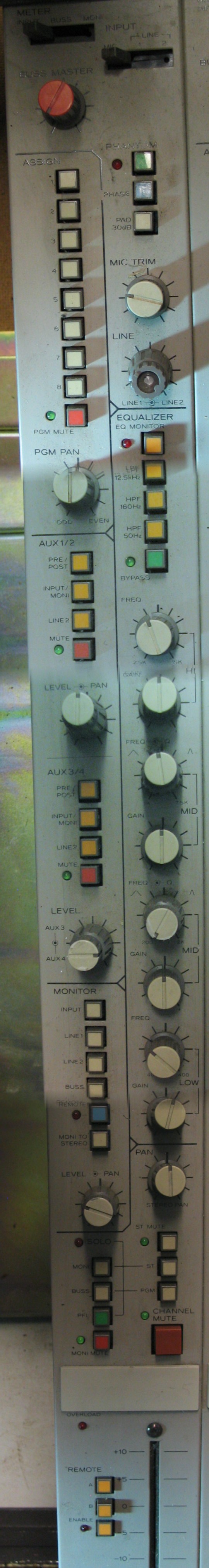
This really threw me for a loop and it was getting late and I think I was starting to circle the tree looking for hefalumps (for those of you Winnie the Pooh fans). The BUSS source switch appears to source the BUSS IN jack, and not the PGM groups. I was starting to wonder how to monitor the PGM groups, like where is the AFL or PFL function y'know? There is a "PGM" switch in the SOLO switchrack, but that didn't seem to be working. More on that later. Anyway, I need to do more testing of this and I'll need to find a way to do it with multiple sources of program material so I can easily know what is going where. If the ASSIGN section sources the INPUT, and then propogates to the BUSS MASTER knob and then to the BUSS OUT jack, how does it ever make it to the STEREO buss? The INPUT source automatically goes to the STEREO buss, and you can get the BUSS IN jack to the STEREO buss by sourcing the BUSS in the MONITOR section and then latching the MONI TO STEREO button (and this was kinda cool because it is not affected by the ST MUTE or CHANNEL MUTE buttons, so in that way the BUSS in jack can be a clean direct drop to the STEREO rail...dunno if latching the STEREO TO MONI switch defeats other signals being sent to the STEREO buss or not...didn't test that). Anyway, I guess the problem may be with me trying to fit this board into the world of a FOH mixer where you have channels that can be assigned to groups and then the groups can be assigned to the master buss. I suppose if the PGM groups are intended for an 8-track recorder/reproducer then you would monitor off the sync head via the LINE inputs on the M-___ which obviously can be monitored and routed any number of ways...hm. :confused:
  • STEREO PAN pot: straight forward...sources whatever is routed to the ST buss...seems to be working fine.
  • All the crazy SOLO switches and some more MUTE switches: for some reason I was really thrown by this section in the past because of how it is diagramed on the dress panel...like the MONI and ST SOLO switches were linked or something...well, they are only in that they both drive the SOLO indicator light, so they are what they say they are...the MONI, ST, BUSS and PGM solo switches route whatever they are labeled as to the SOLO buss...well, almost. Couldn't seem get anything to the SOLO buss when latching the PGM solo switch, but there might be reasons for that so I've got to try some more things there first. I think the ST SOLO button is a solo-in-place whereas the PFL functions as it normally would as a mono solo pick-off just aft of the INPUT source switch. There are also the ST MUTE, MONI MUTE and CHANNEL MUTE switches in this section, which pretty much do as they are labeled except that there are some things that don't get muted by these switches, like nothing seems to mute the DIRect OUT jack, and nothing seems to stop the MONI TO STEREO function, but again I was getting dizzy and I can't quite recall what was happening by the time I got to this section.
  • REMOTE section: I was really hoping to confirm my suspicions about this section, but alas 'twas not to be...I expected that if you latched the REMOTE ENABLE switch that everything going to the channel fader would be defeated and now the fader would be sourcing the REMOTE buss, the source of which appears to be defined in the master Control Module. Latching the REMOTE ENABLE didn't seem to do anything, and I couldn't get anything to happen when I also latched the REMOTE switch in the MONITOR section, so this whole bit is still "to be determined".

Here's that stitched pic of the entire channel strip that I put up some time ago. Thought it might help to put it here too as reference. ;)
Channel%20Strip%20stitch.jpg
 
Last edited:
Congratulations !!
What amount of work you have put in to this one Sweetbeats :eek:
 
Encouraged by the results of my initial testing, I'm modding some furniture to place the M-___ in my ISO booth...trying to figure out how to squeeze in the BR-20 and 58 or 48 as well...the Yamaha 01X and about 26U worth of gear...I think it can be done and still have the drums in there. I'll be totally surrounded...in other words my drum throne will also be the engineer's chair and I'll just turn 180 degrees. I'll know more as I continue testing channel strips and ultimately the master Control Module, but if things keep going well, I may not be keeping my M-520...need to thin the herd and the M-___ does everything and more that I need...a flexible analog front end and monitor console for the DAW and simultaneously the hub for an 8-track atr and 2-track mixdown deck, and inputs and outputs to spare...
 
Hello. Great work and thread...!...:cool:.. Testament to real dedication and purpose. I suppose I should've sent you my PSU from my Tascam M-2600mII to repair instead of sending it to Tascam. They kept it there for weeks and then say they couln't find anything wrong.! ( and they have schematics!..:mad:..).. Maybe you can sell this design back to Tascam since you actually " made" it..:D..After all is said and done, have you finished this M_ console and how does it sound? Good job..!...:)
 
Thanks! :)

See post 190 for all the detail on where I'm at and answering the "how does it sound" kind of questions...still only one strip tested, master Control Module is in pieces awaiting caps...

And BTW, evm1024 is the guy that needs to "sell back" the PSU design. I merely assisted. ;)
 
bump

Bump for your hard work and stayin' power.
Really great stuff that channel strip lit up is a thing of beauty.
 
Update

I almost have the M-___'s new permanent nest ready. Once I get it moved in there then I can start testing channel strips again. Hoping they all check out I'll start loading them in. Since the master Control Module is disassembled awaiting back-ordered caps I'll put in as many working channel modules as I have and set up a virtual master section using my Yamaha/Presonus A/D/A gear and Cubase. The strips won't be cleaned or anything, but I can at last get them in there and start driving the thing and then one-by-one clean them up, recap and maybe try out some opamp upgrades after I've gotten used to what's under the hood presently.

Might sound silly, but I recapped all the meter amp PCB's...I know that is probably the least critical to anything, but I had the caps on-had to do it, I've got all the meters out of the housing, and it looked like some of them were bulging so I figured I'd take care of it now. Found some suspect connections while I was at it and had a chance to clean everything up and inspect.

I dropped the meter bridge housing off at a local auto-body shop today. For $20 they're going to match the paint, repair the scratches, get rid of the rust and spray all the inner surfaces I primered. Pretty good deal AFAIK since I've wasted a bunch of time trying match the paint color and sheen...I'm going to keep my day job. My attempts looked bad. Once I get that back then I can reassemble the meter bridge and mount it on the frame and do a smoke test on that, and then test it with a channel strip.

That's all for now.
 
  • Got the meter bridge housing back from the body shop...I'll have a little tweaking to do with the sheen, but the color matching is incredible. I'm pleased.
  • Inspected all the meter amp PCB's and cleaned the meter lenses...ready to hook 'em up and see some bulbs glow...

Here's a pic of the future humbl perch of the Tascam M-___:
The%20Perch.JPG


And here is a view that shows the perch's proximity to the drum kit... :o:
The%20Perch%20and%20Drums.JPG


Got the onto the perch, and hooked up the 6V and associated 0V rails and voila! All the meter lamps look really healthy! :)
Meter%20Lamps%20Work.JPG


Next step was to hook up the +/-15V and associated 0V rails. I did that and...
 
Last edited:
Shoot!

When I power it up with all the power rails to the meter bridge connected the peak LED's stay lit, and the dementedchord Idiot Light glows slightly:
Meter%20Problem.JPG


:(:(:(

I have done the following so far...

  1. Made sure the rails going up the meters checked okay
  2. Reinspected the trace sides of the meter amp PCB's for any shorts

I did find some spots that seemed a little suspect, but that didn't change the problem...

Suggestions anybody?

The problem only occurs when the +/-15V and associated 0V rails are connected...all the meters peg when it is first powered up, and the peak LED's stay lit...

I guess the next thing would be to disconnet all meter pairs except one and see if the problem goes away, and then reconnect pairs of meters one at a time to see which one sets it off...just hate to desolder all those cross connect points, especially if there is another logical test that could be tried...:confused:
 
Last edited:
the purpose of the light i is to test for hard shorts... a glow is not a problem on start-up especially where inrush current can be an issue... as it is here with the total number of devices... so after you check it take it off the light cause it can keep full voltage from getting into the unit... if you're worried while adding channels you can always hook up and unhook as ya go...
 
demented....yeah, I get that part, but there are very few compenents inline right now...no channel strips or master section, just the IC's on the meter amp PCB's and the lamp glows constantly, not just on startup, and the meters spike when you first switch it on, and the peak LED's are always on. I've got a problem. :(
 
Back
Top