sweetbeats
Reel deep thoughts...
Must have been one of those days
Hm...
") ...but...isn't it always one of those days? It is for me anyway...
...but...isn't it always one of those days? It is for me anyway...
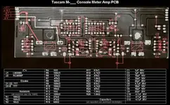
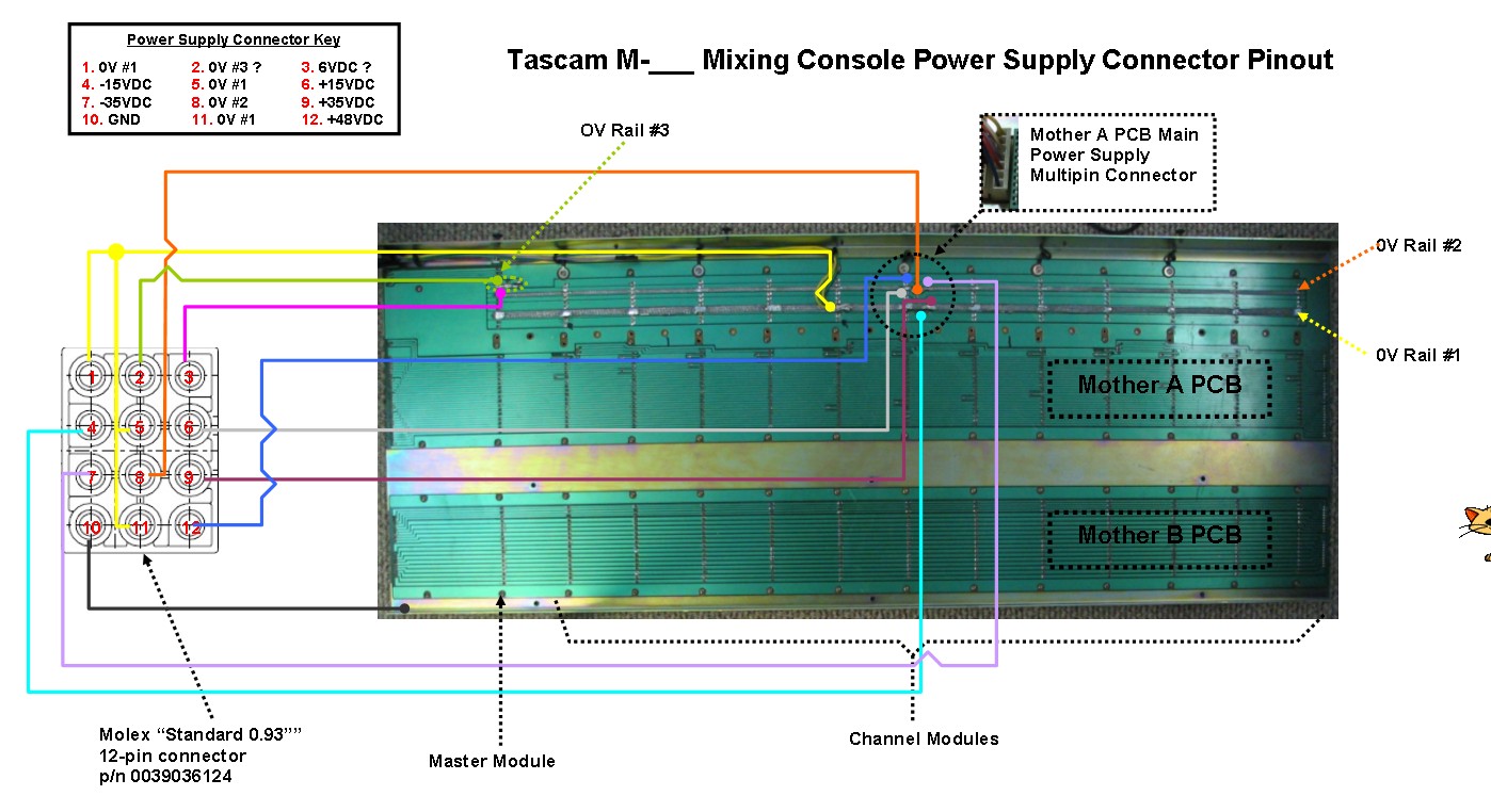
Maybe sometime today I'm going to put up a post with a pinout of the power connector at the mixer and a rough schematic of where the 12 conductors go...its getting a little more complicated for me because of what I discovered last night...the meter amp PCB's are not simple like on the M-520. In other words, I'm pretty sure that my two unknown power supply connectors are not 11VAC...the traces for the meter bulbs are relatively interconnected with the 0VDC and +/-15VDC lines that also go to the meter amp PCB's, so...

Back in the saddle.
What I then did was double-check to see if those two unknown lines went anywhere else...they do after all go to the Mother A PCB. I had recalled that they went to the Mother A PCB but then only up to the meter bridge and that was one of the things that got me hopeful that it was 11VAC. My memory was flawed. Must have been some of those days.

Those two lines are isolated to the meter bridge and the master module though...they don't go to the channel modules. So I started following where they go in the master section. Fortunately they did use the same wire type and color all the way through...the two lines go to each of the four PCB's in the master module...and then I saw it. On the Studio PCB and Control Room PCB they are labeled.
 "0V" and "6V". Now...I noticed something else, and I can't believe I missed it before. All 4 master module PCB's and the Balance Amp PCB's are labeled with part numbers.
  That's another topic and I'm going to wait to go there for a moment. My concern is that those PCB's then may or may not be custom fabbed for this console, which could mean that the labels are not correct. You follow me? I don't want to assume that the labels are correct, hook 'er up and fry something and delay power-up by who knows how long. Been there, done that. So I think I'm going to need some help. My brain quickly gets muddled when I start following traces and components. Its going to take some time to develop that skill I think; to reverse engineer a PCB, but I think its going to be necessary to some degree.
  :rolleyes:") So at this juncture I'm hoping that if I post up some details about where these rails go it may trigger some affirmation that they are indeed 0V and 6V. That should be easier than trying to determine the voltage from nothing (i.e. looking at the circuit to determine if it couldn't be 0V and 6V may be easier than looking at a circuit and being able to know the voltage type and amount...process of elmination). I do know that the peak LED's in the VU meters are tied in with these two rails.
So at this juncture I'm hoping that if I post up some details about where these rails go it may trigger some affirmation that they are indeed 0V and 6V. That should be easier than trying to determine the voltage from nothing (i.e. looking at the circuit to determine if it couldn't be 0V and 6V may be easier than looking at a circuit and being able to know the voltage type and amount...process of elmination). I do know that the peak LED's in the VU meters are tied in with these two rails.Now here's the next thing. I'm getting confused quickly here. There are actually 3 separate 0V rails and a ground. On the power supply connector three conductors go to one 0V rail, one goes to a second, one goes to a third, and one goes to ground. Half that power supply connector is populated with the 0V rails and the ground! My growing confusion is over how to interface that with the 0V rails in the PS-520, which has two of the 0V rails and a ground conductor.
So some time is going to have to be put in on this. Not as close to power up as I was thinking.
I'll put up a sketch later of the pinout for the power connector.
")