briank
analog for the people!
What the hey, I'm game 
")


I must admit, sometimes I just open the headcover and flip down the gate just because...
")
I must admit, sometimes I just open the headcover and flip down the gate just because...
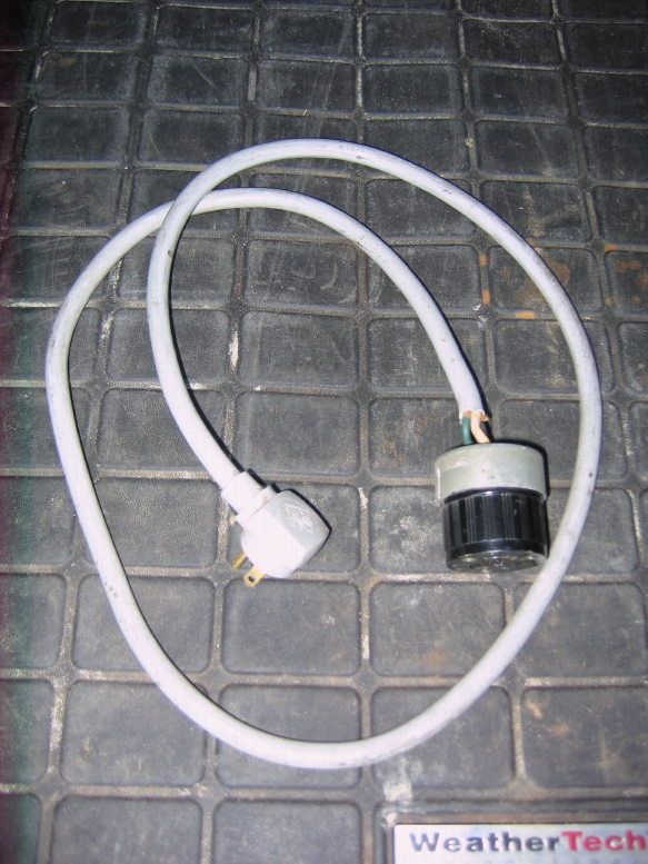
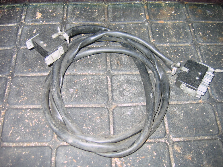
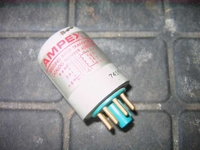
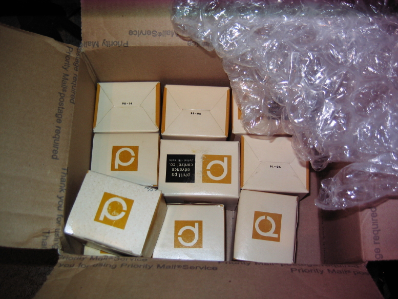
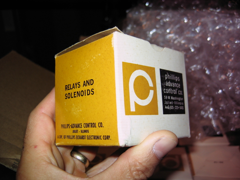
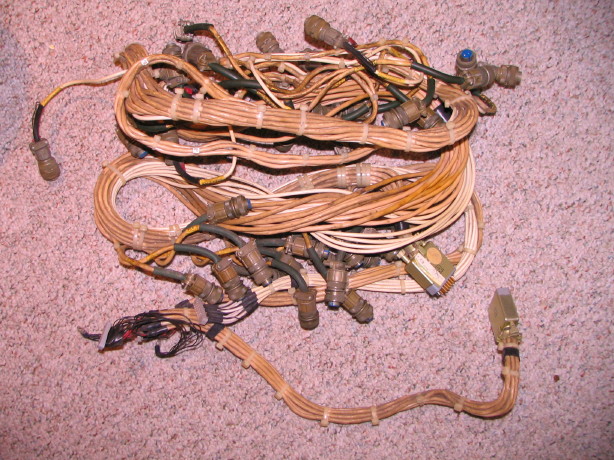
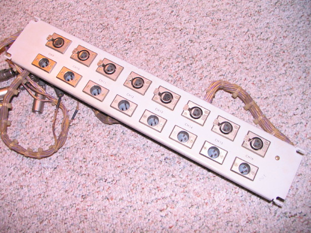
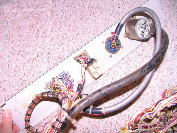
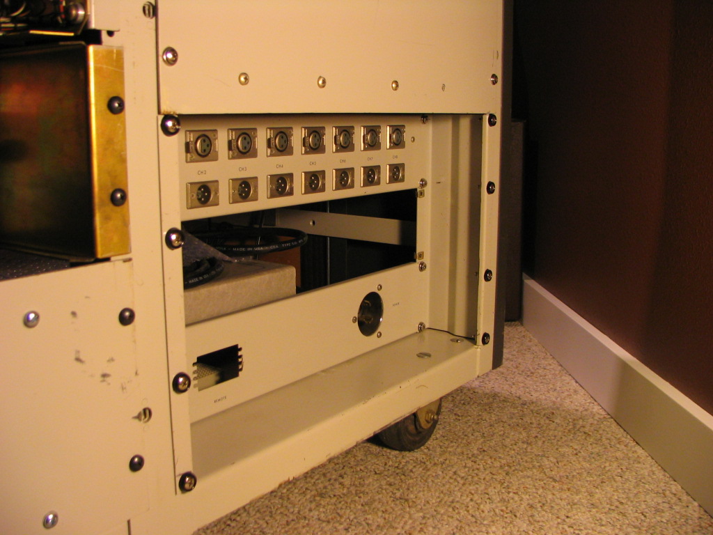
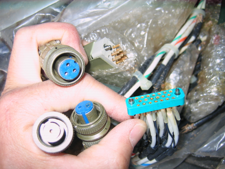
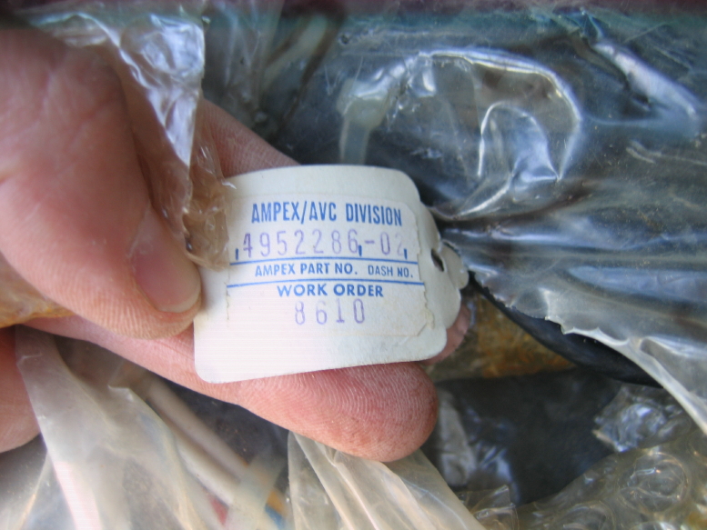
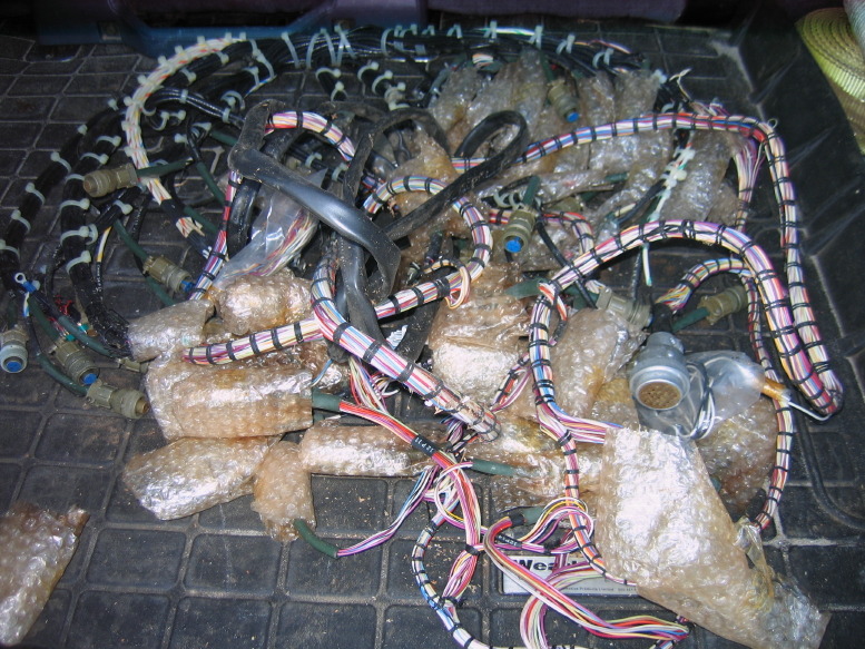
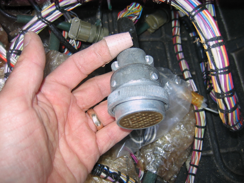
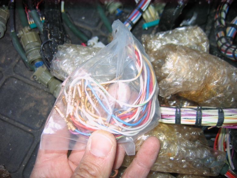
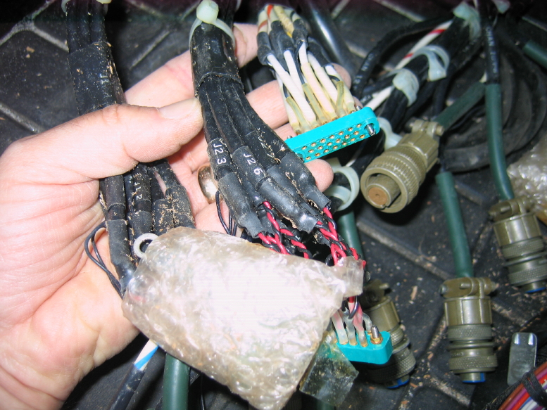
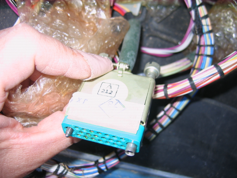
 So I'll hang on to them until I'm certain of what all I need or feel I should hang on to for spares and sell the rest, but needless to say I'm swimming in mil-spec connectors...
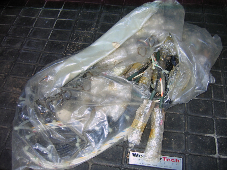
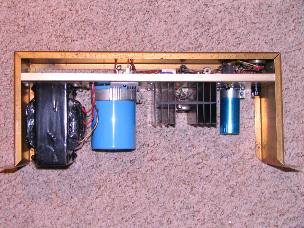
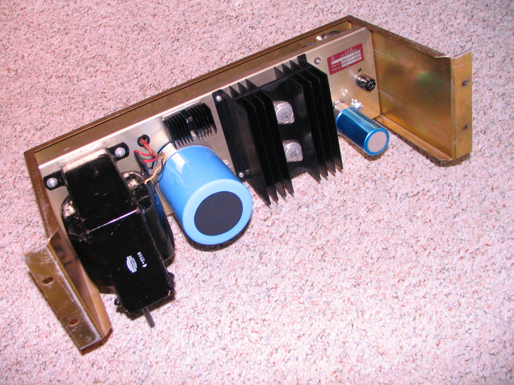
 , and then pulled the other 39V supply and replaced that same cap because it was also in backwards and I'm sure has taken a beating even though it hadn't blown yet. Got both supplies back in.
What doesn't feel good is that there are only about 3 channels that consistently will enter record mode, a couple that are intermittent, and 3 that just won't...my intermittent PLAY problem is getting worse too. *sigh*
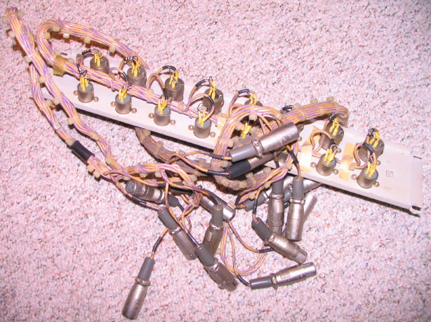
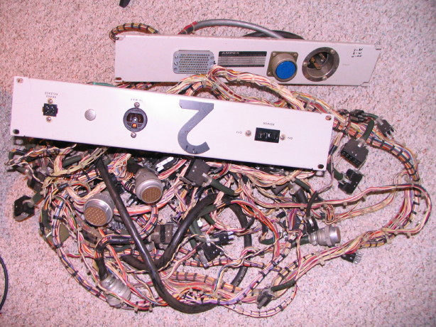
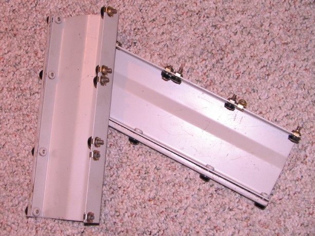
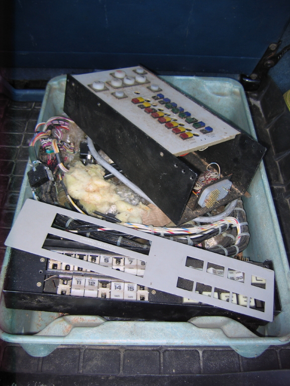
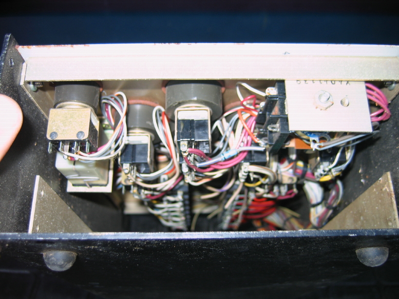
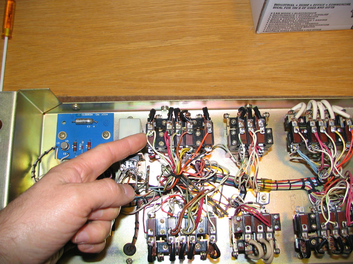
I'm pretty sure I'm gonna have to pull the relay box and tear into that.

Cory, really great to hear that you got the power supply sorted and that you scored those relays for a steal of a deal! I too feel the relays, once replaced, will solve many problems. I think overall very positive news.
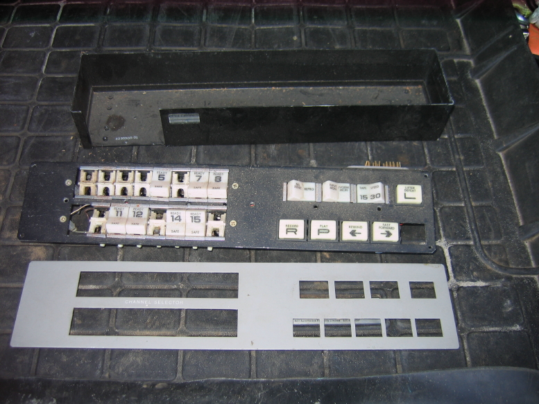
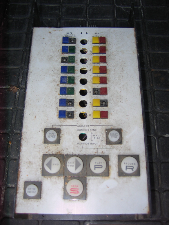
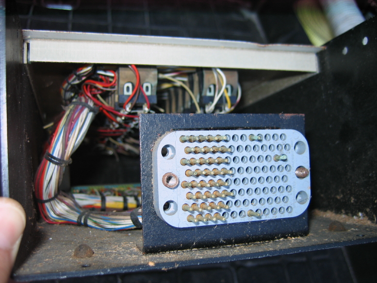
), with the aforementioned wiring repairs as well. I am going to heed some additional recent advice to make the changes in steps to limit the troubleshooting if something doesn't go right. I'll start with replacing just the PLAY relay and test that, and then move on to the record relay and then the others one at a time. I actually think there's enough room in the console that I can pull the relay box out just once, remove the shield that covers the tension resistors (the ones that are the size of a Coney Island hot dog), and then be able to get to all the relay mount screws from the back so I don't have to pull the relay box in-between each relay. Not that it is a big deal, but if I don't HAVE to pull the connectors from the box and pull it out and put it back in 8 times I don't want to. The connectors are heavy-duty but why test their endurance if I don't have to? I WILL pull the output of the 24V power supply though...I figure with the transport connected the filter cap in the power supply drains fairly quickly, but I'm just a bit wary at this point...I can recall having a supply cap arc on me once when I thought there was no way it could be charged still (DUMB), and with my recent exploding cap saga I have to say I'm just a little bit more jumpy around my electronics these days, which, really, is a very good thing. We should all take GREAT care around this stuff. If the lid hadn't been fastened on the 39V supply that had the cap blow it could have caused SERIOUS injury, and that was the "small" cap. You shoulda seen me when I power tested the repaired supplies the other night...ear protectors on...safety glasses...double checking the covers tightly secured...shield barrier in place between me and the guts of the console...seriously, if I owned a flak jacket I'd have probably put it on. Again, it was a 500uF cap. Not small, but not huge either, and after it blew all the cymbals on my kit were going "ahhhhhhhhhhhhhhhhhhh". It go bang.