Ampex MM-1000 Story...

  • Thread starter Thread starter sweetbeats
  • Start date Start date
Boy Cory, you've mentioned in the past how you didn't relish dealing with control logic issues like I did with the MCI machine, but reading your last two posts gave me some transport control flashbacks alright :P In your case it's looking at voltages through relays, in mine it was probing IC pins. I know squat about Ampex transports, I wish I could help advise there! It's too bad it doesn't seem to be something simple like dirty contacts, I know firsthand how oxidation can cause gremlins.

Yeah...I kind of realize that its just two flavors of the same issue but I think for me I start getting lost when looking at the schematic of a logic circuit with IC's because there's a whole 'nuther layer down below what's on the schematic with the IC's. You can see the ins and outs of the IC but then you have to pull the spec sheet for the IC to understand what those pins do. I suppose if I dealt with a particular set of IC's on a frequent basis it may be different in that I'd have the pin functions memorized like I do for standard DIP-8 opamp packages...its just a matter of working with them, but a 14-pin comparator chip is just alien to me and I sort of get stopped-up going back and forth between the pinout for the IC and the schematic. Maybe someday, and only if necessary. For now its great to see everything all on one layer and to be able to go to the physical assembly and see/touch all the stuff displayed on the schematic.

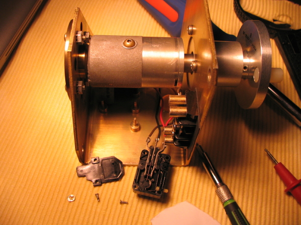
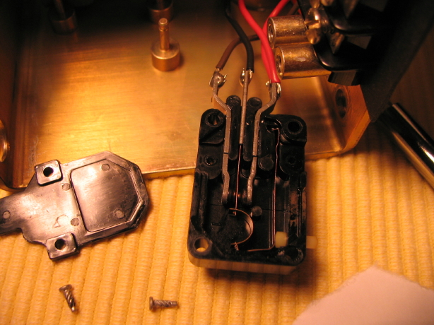
I did some more gazing of schematics...the control box, control panel, transport, mode control schematics and the wiring diagram that ties them all together. Again, though it is mentally strenuous for me at times, these kinds of problems really ultimately bring a level of comfort and familiarity with a device and I am enjoying this level of acclimation with the Ampex. At this point I have a suspicion that the connection between the +24V power rail and the PLAY button may be needing some attention. After studying the above schematics I understand that what is happening is indeed outside the control box because when I route power to the appropriate places within the control box everything works like a charm, and that what is happening when there is a delay in the transport actually dropping into PLAY mode after the PLAY button is pressed is the exact same thing it would do if the supply reel wasn't stopped yet...if you are fast-winding, for instance, the motion-sense assembly (which ain't a fancy thing really from an electronic standpoint...just +24V in and two microswitches that route the power one place when the motor is turning and another place when it ISN'T turning) blocks power from getting to the PLAY button. If the tape is still coasting to a stop from a fast-wind mode you don't WANT the pinch roller dropping in. Duh. So K4 latches and puts things into a ready state, and then as soon as the transport comes to an actual stopped state the motion-sense assembly switches route power to the PLAY button which then goes to the appropriate terminals on K4 which are closed with K4 in its "ready state" and that then closes K6. Well, if there is anything sketchy in the path from the +24V supply to the motion-sense assembly to the control panel to the relay box then there will be intermittency in K6 closing. I betcha there are dirty contacts or bad connections somewhere in there. There is actually quite a bit of wire and quite a number of connections that are in that path. I replaced the motion-sense microswitches so I'm pretty confident that all those connections are good but it won't hurt to check those. Its all guilty until proven innocent here. I'll start with simple continuity testing from the +24V supply out to the relay box to pin 19 on J2 of the relay box with the PLAY button depressed and see how many ohms I get there and then chase it down assuming it is not a healthy short. Grounding too. Need to check that. Its gotta be in there somewhere, the culprit, and armed with a deeper understanding of how the different systems interact to perform the simple function of PLAY mode I will find it...and its even fun.

But NOW I must go see a video of an MCI 1" 8-track!
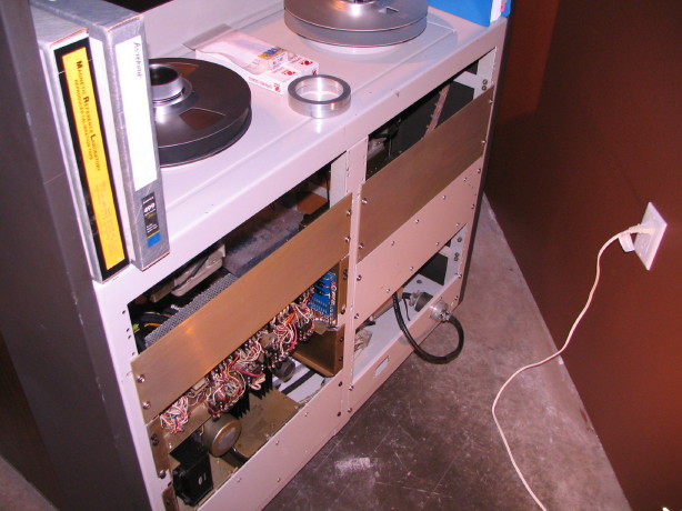
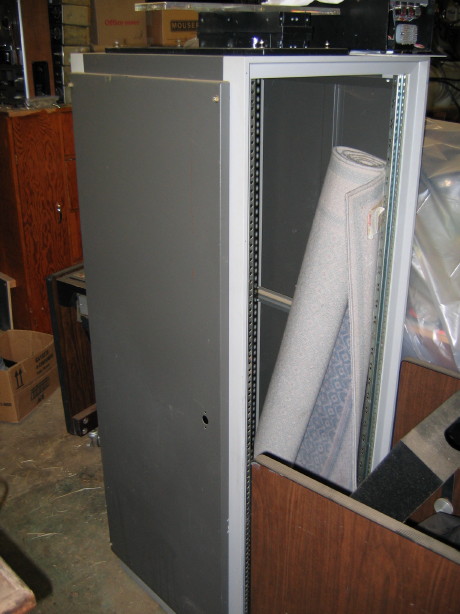
 :D
 
Cory, forgive me if this was mentioned or discussed before but do you know if the MM-1000 has germanium transistors?
 
Hm...dunno. I think it was after that era. Do you know how to tell, and what would that mean?
 
Well, not sure how to tell exactly but germanium based electronics are known for their unique tonal qualities, have a "crunch" sound that many like. I know that some early Ampex, Scully, Nagra and Uher machines had those. I guess I was just wondering if yours had germanium inside.
 
Ah...Okay...Yeah I think I've read about that too. I'm thinking probably not gonna be found in my machine...I think earlier Ampex machines did but I don't know which ones...I DO know that at one point I want to check and see if my meters have germanium resistors in them because I guess meter distortion entering the signal path was less of an issue, but I have a feeling I won't find them in there.

Interesting question.
 
I believe I've found the problem...when I checked the resistance from the output of the 24V supply to the input on the relay box that comes through the motion-sense assembly to energize K6 when the transport is motionless I got about 10ohms...seemed too much. I can see maybe 1.5ohms due to all the connections and wire length ans switches, but using Ohm's Law if we assume the voltage is constant (for the sake of simplicity) then a change from, say, 1ohm to 10ohms would have a reciprocal effect on the current by a factor of 10...that could certainly cause problems since we are dealing with large mechanical relays. I narrowed the point of resistance down the the motion-sense assembly itself. The resistance from the input to the output of the stopped-state terminal of the motion-sense assembly is 9ohms...input to moving-state output is 0.2ohms. Good to have a prime suspect, though I'm not looking forward to (again) pulling the motion sense assembly out.

Stay tuned.
 
Well, I traced the delay problem down to the switches in the motion-sense assembly. That's where power comes from to energize K6 through terminals 6 and 7 of K4 when the transport is not moving. The problem was that one of the two micro-switches in thh motion-sense assembly was acting as a 10R resistor when the transport was static. I used Ohm's Law to figure that at a constant voltage a change in the resistance by a factor of 10 (assuming at least 1R resistance when things are working normally) would result in a reciprocal decrease in current by a factor of 10 which I figured was making the current level juuuust on the fence to energize the coil of K6.

I had done work on that assembly detailed some time ago in this thread...quite a bit actually...totally cleaned it of old Dow Corning fluid and replaced with new...completely disassembled and cleaned, new top bearing and a new switch to replace a mangled one. Funny thing is that it was the new switch that was acting as a resistor. I figured out how to open the switches up and then used DeoxIT, strips of paper, canned air, etc. to clean and polish the contacts and it is working sweet now.

Problem is the transport *still* won't latch into PLAY mode. Only when holding the PLAY button. It wasn't doing this before I replaced K4 so it HAS to be something I did but I can't figure it out yet. Its confusing because K4 gets holding current through terminals 3 and 5 of K3, the STOP relay, but, at least according to the schematic, K3 gets energized along with K6 when you hit the PLAY button which breaks the holding current to K4 so I'm not sure how it works because if K4 opens then I don't see how K6 can get energized and held. K9 is involved but I haven't got that into my head yet how that works.

So, bit by bit. Being careful to limit changes so it is easy to revert if needed if something isn't right and work that out before moving on. I have looked and looked and looked to see what if anything I did different as far as wiring the new K4 relay up and I can't see any difference. If I manually actuate K4 everything works fine, so it is related to the actuation via the PLAY button that is causing the trouble. At least the delay problem is gone.

Anyway, here is the motion-sense assembly (again) and then a closeup of one of the switches opened up.

IMG_2409_1_1.JPG


IMG_2408_1_1.JPG
 
Relay Box Cover Is On The Way!

Thanks to Steve at Sonicraft a rare MM-1000 relay box cover is on the way.

Thanks to Steve for diggin' it up and being willing to part with it!

I may not have the relay problems licked yet but at least Matilda will LOOK good! :p

And this way I can just cover up the relays and not look at them if I get too frustrated trying to fix the problem. :D

Just to refresh your memory, the back of my MM-1000 looks like this:

IMG_0754_8_1.JPG


Notice on the left side the whole mess of wires. That's the relay box. With the cover it will look something like Sonicraft's "Phatzilla". Not as clean, but covered. :) Here is a shot back when "Phatzilla" was in progress. You can see the cover on the relay box. The open module below the relay box is the transport power supply and that is normally exposed like that.
 

Attachments

  • MM1000_halfdone_Back_4Cory.webp
    MM1000_halfdone_Back_4Cory.webp
    35.8 KB · Views: 74
I stumbled across this recently, read all 57 pages, and signed up to follow further work. Very cool.

A small tangent - does anybody know where all of the electronics went for 24-track operation? It doesn't seem as if there's enough rack space down below for 16 channels of electronics. And, related, here's the first AG-1000-16 at Mirasound with no overbridge (can't see all of the electronics, though):

27890021_2.webp

The 1968 AES handout from Ampex even shows an AG-1000-24 with no overbridge, although the doors are closed so you can't see the electronics. And there's an AG-1000-16 with all 16 channels below (apparently the first one, installed at Mirasound) but it indicates the configuration is different than subsequent models. Looking at photos of Phatzilla, it seems like there's only room for 14 channels below, with all of the other panels moved/removed.

Am I missing something? Was there a slightly larger chassis available?
 
I tried putting in a few links to things, but it looks like I can't do that until I've made 5 posts. I'll try to post them when I get there. That AES handout is online, and I was going to link to the blog that photo came from and Phatzilla.
 
I figured the chassis would have been redesigned for 24 tracks - this model basically being a Quad video deck after all.
 
I figured the chassis would have been redesigned for 24 tracks - this model basically being a Quad video deck after all.

My assumption was it would be the same, but I don't think I've seen a picture of an MM-1000-24, at least in full. There's a photo of what claims to be a 24-track machine at Mirasound (probably early 1969), but it is only from the transport up (there is an overbridge), and it *looks* like there are only 16 track selector switches on the panel. That said, that in and of itself is odd, since the original machine, as above, had no overbridge and had all of the switches in a row, rather than in two rows.

I'll post a link to that too...
 
Another MM-1000 fan WOO-HHOOOO!

Glad you enjoyed it, lukpac (the thread)...you get a freaking gold start for wading through it all. :eek:

Okay...no the chassis was not redesigned for the 24-track model...the Mirasound AG-1000 chassis was prototype to the core and the chassis was a little different on that to accomodate the 16U of electronics per side.

On a side not that AG-1000 was for sale not too long ago...don't know if it ever sold but here is another picture showing the full monte:

AmpexDSC00784.jpg


The standard configuration for the 24-track MM-1000's was a sidecar rack with the additional 8 channels of electronics...so 16 in the transport chassis and 8 externally mounted. Here is a drawing from the training manual of what I'm talking about...I've never seen a picture of a real live 24-track MM-1000:

MM-1000%2024-Track%20Configuration.jpg


I actually have one of those sidecar racks...

IMG_8445_1_1.JPG


So that was the standard configuration for the 24-track model.

Do you have any way to scan and upload a copy of that '68 AES Ampex Handout on the MM-1000???
 
Very cool stuff. I think I've seen that shot of the rack with the additional channels before, probably upthread.

The board said I needed to have 5 posts in before I could post links. Let me see if that means "on 5" or "after 5"...
 
My assumption was it would be the same, but I don't think I've seen a picture of an MM-1000-24, at least in full. There's a photo of what claims to be a 24-track machine at Mirasound (probably early 1969), but it is only from the transport up (there is an overbridge), and it *looks* like there are only 16 track selector switches on the panel. That said, that in and of itself is odd, since the original machine, as above, had no overbridge and had all of the switches in a row, rather than in two rows.

I'll post a link to that too...

Again, keep in mind that that original machine was very protypical. There were a number of things that were different about it over the production MM-1000 machines including the control panel layout, the lack of sync relay boxes, differences in the tape path, etc. The Mirasound machine claiming to be 24-track could have had the 8-additional electronics in an outboard rack with an 8-track remote used for track arming, OR the track arming may have just been managed at the electronics modules ala Ampex 440...same electronics modules and on the 440 you do your arming and monitor source selection at each amp module...the MM-1000 just remoted those controls to the centralized location on the control panel. Factory MM-1000 24-track machines had two rows of 12 switches on the control panel, 16-track machines two rows of 8, and 8-track machines a single row of 8. I have some 24-track mode control switch arrays. So I'm conjecturing here but the Mirasound "24-track machine" may have been the same prototypical AG-1000 16-track machine with a sidecar rack of 8 more modules and a 24-track headblock. Done. All the arming and monitor source selection can be done from the electronics modules even on a regular MM-1000 machine. The mode controls on the control panel are duplicative to the controls on each amp module.

As far as I can tell the quad video machine that they based the AG-1000 and subsequently the MM-1000 was the VR-1100E which was a compact format chassis pictured here:

Ampex%20VR-1000E.jpg
 
Last edited:
I sent you a private message with all of the links. Can you repost those here in the thread?

FWIW, the prototype AG-1000-24 as seen in the AES doc has 2 rows of 12 switches...
 
Outstanding!

Thanks lukpac for sending me the links and I gladly post them here.

First one is the 1968 AES Preprint #583 which details the 2" mastering recorder which ultimately became the MM-1000.

Note that the chassis is CLEARLY a modified VR-1100E as noted above. The pictures on pages 8, 9 and 10 of the pdf are different than the machine pictured on page 7, the 24-track machine. I believe the machine pictured on pages 8, 9 and 10 is actually the Mirasound AG-1000, and the machine pictured on page 7 may be the same machine or a different prototype but I believe it is a mock-up. Notice they don't spend much time on it, I don't think the 24-track heads had been manufactured yet...it is a foreshadowing of what is to come but I don't think that machine on page 7 is a ready-to-go 24-track machine. To be honest I wouldn't be surprised if the "24-track machine" on page 7 of the pdf isn't actually just a VR-1100E with a modified control panel.

Here's the document available thanks to the fine folks at recordist.com, home of the Ampex List...I can't believe I've missed this document before!!!

http://recordist.com/ampex/aes-preprints/aes_preprint_583_1968-03_master_recording_two_inch_tape.pdf


I've certainly referenced Steve Puntolillo's "Phatzilla" at Sonicraft a number of times but not sure if I ever put up a link...here it is:

Tech Info: Sonicraft A2DX Lab - PhatZilla: the Ultimate Analogizer

A blog which features a collection a fabulous photos taken by the esteemed George Schowerer including the famous one of day one of the AG-1000 at Mirasound:

chameleon:

A collection of Mirasound clippings:

Mirasound Studios*: un album sur Flickr

And the clipping that references a 24-track MM-1000 but only has 16 mode control switches (as I mentioned above this could certainly be a factory 16-track machine upgraded to 24-tracks by virtue of a 24-track headblock assembly and 8 additional electronics modules outboard with necessary cabling...totally feasible, OR its just a 16-track machine and they used photos of it rather than the 24-track because that's what they had available...ORRR...they mislabeled the photo caption):

Mirasound Studios | Flickr*: partage de photos*!

And last but not least a cool Billboard entry from 8/9/69 describing the first commercial release recorded on 24-track (done at Mirasound):

Billboard - Google Books

Thanks again, lukpac, for sending the links!! ;)
 
Last edited:
Glad to provide some input. Regarding the AES doc:

First one is the 1968 AES Preprint #583 which details the 2" mastering recorder which ultimately became the MM-1000.

Note that the chassis is CLEARLY a modified VR-1000E as noted above. The pictures on pages 8, 9 and 10 of the pdf are different than the machine pictured on page 7, the 24-track machine. I believe the machine pictured on pages 8, 9 and 10 is actually the Mirasound AG-1000, and the machine pictured on page 7 may be the same machine or a different prototype but I believe it is a mock-up. Notice they don't spend much time on it, I don't think the 24-track heads had been manufactured yet...it is a foreshadowing of what is to come but I don't think that machine on page 7 is a ready-to-go 24-track machine. To be honest I wouldn't be surprised if the "24-track machine" on page 7 of the pdf isn't actually just a VR-1000E with a modified control panel.

You may very well be correct about the 24-track prototype just being a mock-up, especially considering the doors are closed and there's no overbridge for more channels.

As far as the others go, it appears that is in fact the Mirasound AG-1000-16. Notes, on page 5:

"Figure 2 shows the first Ampex AG-1000-16 with the transport in its raised position. The external head cover is removed for clarity. This was the first 16 channel recorder built hence, some items (i.e. erase head, monitor selector switch, mode selector switches and electronics) are not exactly as described in the text.

Figure 3 shows the top view of the same AG-1000-16 pictured in figure 2 but with the tape threaded to show the tape path.

Figure 4 shows the electronics of the first AG-1000-16. As mentioned earlier, this is not exactly the configuration now used or described in the text."

Having come across all of the Mirasound information recently, I'm mildly amazed how early their equipment was in use, notably late summer/fall 1967 for the 16-track, and spring/summer 1969 (at least) for the 24-track.
 
Back
Top