The Transformation Is Complete!
Insert the wild cackle of a mad scientist now...I can't say "its alive yet", but the mods to the power supply are now totally complete.
To bring us up to date, Ethan (evm1024) bypassed the 18V regulators in the Tascam PS-520 allowing the "35V" (in quotes because its running about 26.5V) to pass to the mixer since with the M-___ the 18V regulation occurs in the mixer, like, all over the place, rather than in the PSU as with the M-520/PS-520 combo.
Ethan also did a fine recap job on the Power Supply PCB.
")
As Ethan and I discussed and agreed, the regulators and all the wiring were left in the PS-520 so that it could quite easily be converted back to stock if needed.
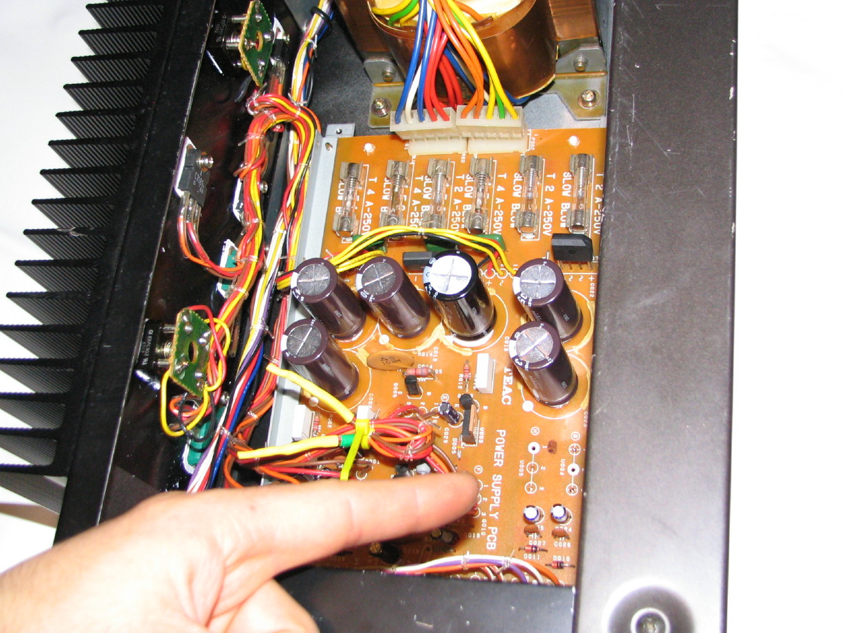
Here are the regulators still attached to the heatsink:
And here are the wires bundled and protected:
And here is where they used to connect to the Power Supply PCB:
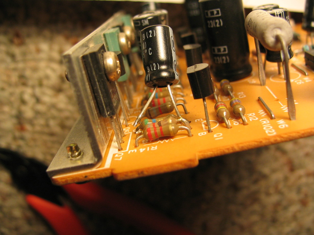
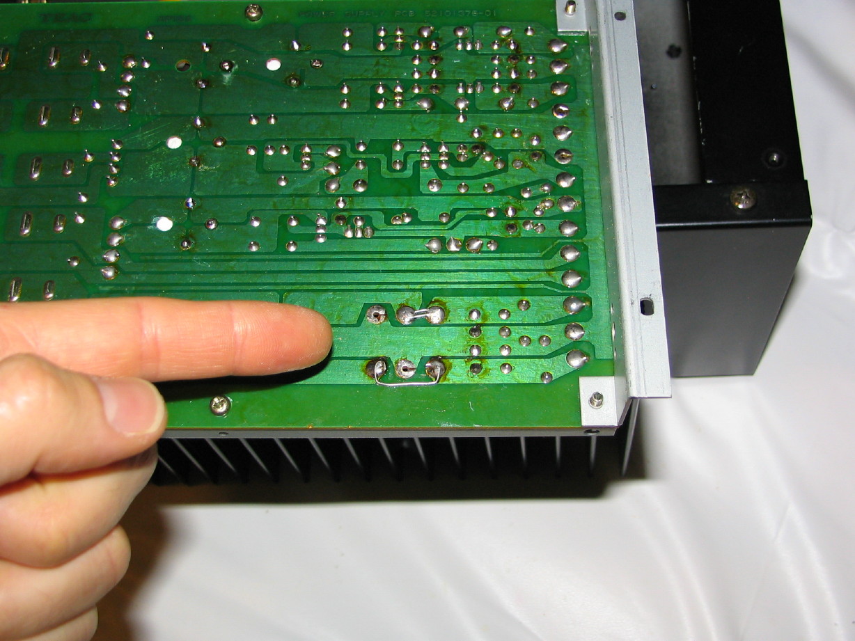
And here is the underside of the PCB...the wires were simply removed and the "IN" and "OUT" pads for the regulators were jumpered:
Now...this is where things got a little interesting. If you've followed the thread you'll know that I have agonized somewhat over the whole 0V rail thing...schematically two of them coming out of the PS-520, but three needed for the M-___. Then recently I looked again at the PS-520 schematic and confirmed that all the 0V rails do indeed tie together in the PS-520, and that there are
two more terminals for 0V rails on the Power Supply PCB! That made it easy in my mind as the M-___ wouldn't need the 11VAC rails, so, internal to the PS-520, those wires could simply be moved to the two open 0V terminals on the Power Supply PCB and then those additional 0V connections would be carrried to the mixer over the wires which carry the 11VAC rails for the M-520/PS-520 combo. Well, the schematic doesn't match the production PCB entirely...no big whoop, but it is interesting to me nonetheless.
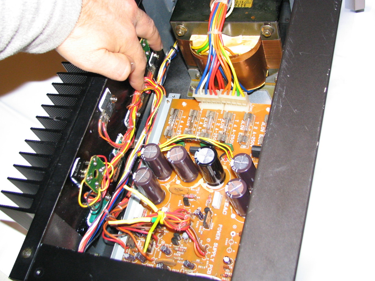
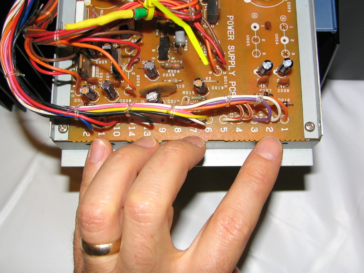
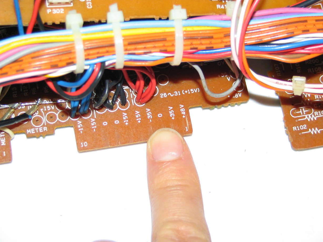
The schematic says that terminals 13 and 14 on the Power Supply PCB are open and connected to the 0V buss. Looky here at a picture of what they actually did at the factory:
My four fingers are pointing to 0V/GND connections. My pinky finger is pointing to terminal 11, which goes to the mixer chassis ground, even though it is physically associated with the 15V rails on the Power Supply PCB which are in terminals 10 and 12.
My ring finger is pointing to terminal 13 which is connected to the PSU chassis ground. This is supposed to be on terminal 9 leaving 13 and 14 open. No matter, its all the same buss, and terminals 9, 13 and 14 are even graphically and physically grouped on the PCB. So 9 and 14 would be the new home for the third 0V rail using the wires originally connected to the 11VAC terminals 4 and 5.
My middle finger is pointing to terminal 7 which is the 0V "0V(D)" rail physically associated with the 6V rail on terminal 6. This 0V rail is connected to scads of LED indicator circuits in the M-520 and even the headphone opamp.

I didn't follow it all the way through the mixer, but it is clearly primarily non-audio related circuits.
My index finger is pointing to terminal 2, which is the main audio 0V rail in the M-520, "0V(C)". It is physically associated with the 18V rails on the Power Supply PCB which are on terminals 1 and 3.
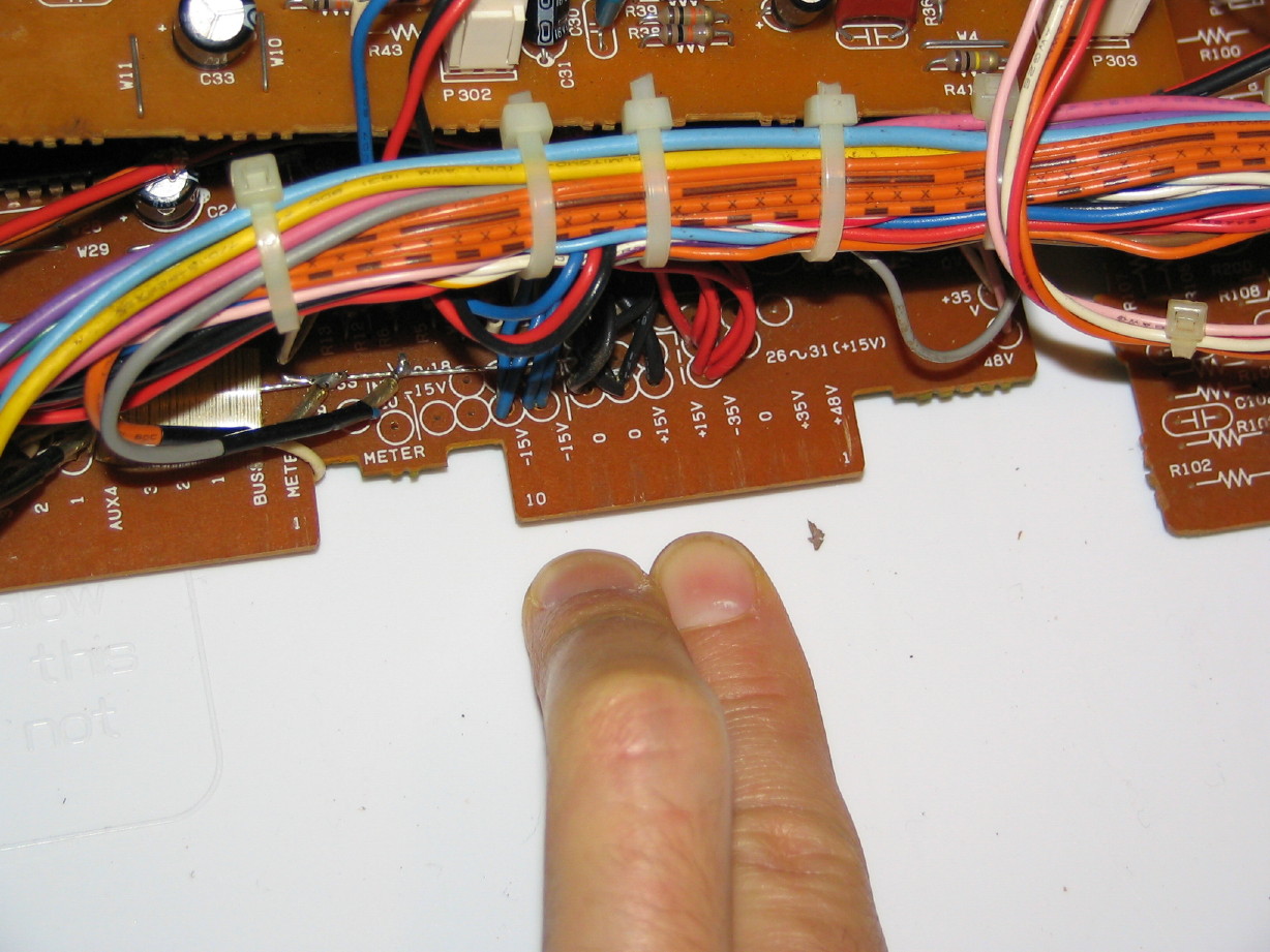
Ohhhhkay. So I started thinking about these physical groupings. I took another look at the Channel PCB's for the M-___, and in particular the (what I call) Input (A) PCB which, for each channel strip, carries all the power and audio connections from the strip to the motherboard. Notice in these next two pictures that there is a 0V rail physically associated with the 15V rails, and another physically associated with the 35V rails. Again, these are two distinct 0V rails circuit-wise in the M-___:
The third 0V rail needed in the M-___ (connection example not pictured), is indeed distinct and physically associated with the 6V rail in the mixer...that pair of rails (the third 0V rail and the 6V rail) only propogates to the master "Control Module" and the meter bridge.
SO...three distinct 0V rails each respectively associated with the 15V, 35V and 6V rails in the mixer...and then looking at the Power Supply PCB again and seeing 0V rails physically associated with the 15V, 18V (now "35V") and 6V rails...so I decided that, rather than use terminals 9 and 14 in the PSU as the third 0V rail I'd have terminal 2 connect to the 0V rail associated with the 35V rails in the mixer, terminal 7 connect to the 0V rail associated with the 6V rail in the mixer, and terminal 11 connect to the 0V rail associated with the 15V rails in the mixer. Then, I'd use terminals 9 and 14 for the connections to the mixer chassis ground rather than keeping that on terminal 11 as it is in the stock M-520/PS-520 configuration.
Don't know if that is right, but it makes logical sense to me.
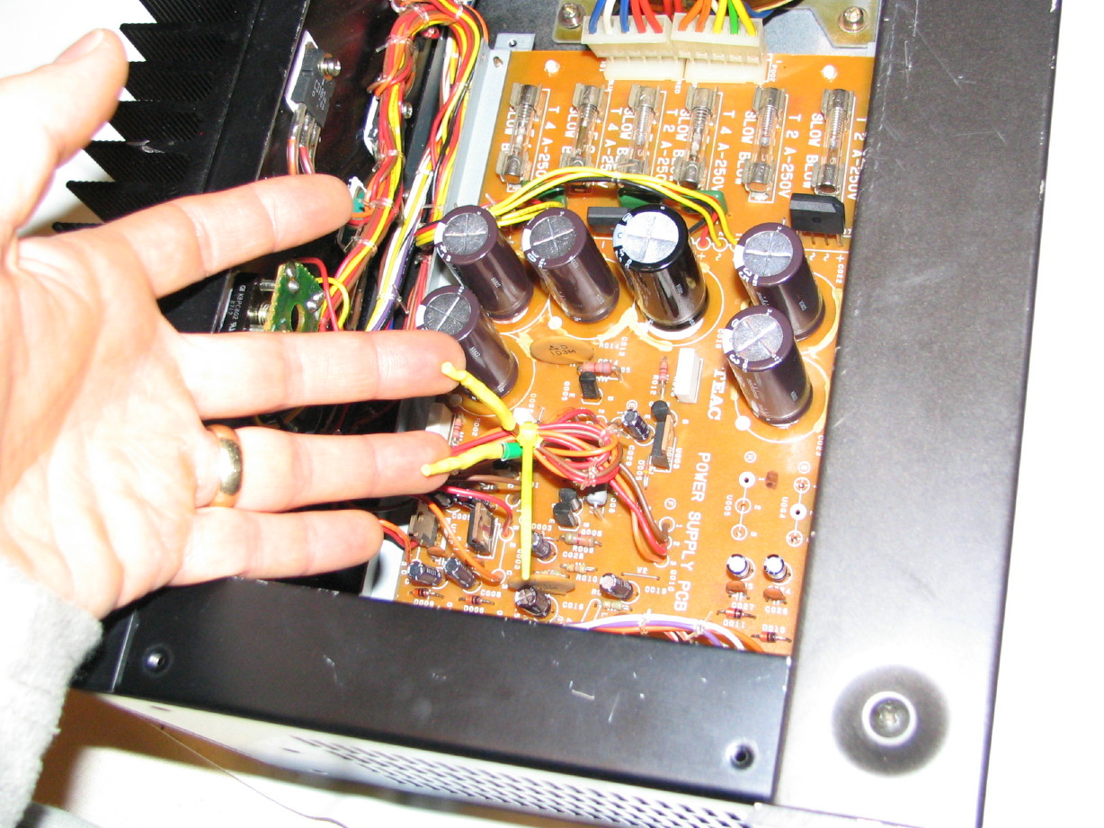
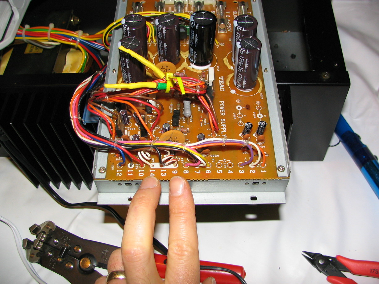
Here my fingers point to the wires coming out of terminals 4 and 5; the 11VAC rails:
And here at long last after my dissertation you see the same wires no connected to terminals 9 and 14 which will connect to the mixer chassis GND over the power umbilical:
After doing this I powered up the modded PS-520 and tested everything to make sure it was all still good, and it is
though I have one question:
The 0V rail on terminal 7 truly seems isolated. When I measure the 6V rail on terminal 6 and put the negative probe on terminal 7 I get approximately 6V...if I put the negative probe on any of the other 0V terminals (i.e. 2, 9, 13, 14 or 11) I get nothing. This baffles me completely since terminals 2, 9, 13, 14, 11 and 7 are all physically on the same buss on the Power Supply PCB...how...does...THAT work???
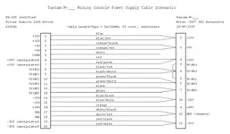
Here is a large .jpg of the Power Supply PCB layout:
https://www.torridheatstudios.com/ftp/share/Documentation/Tascam/Tascam M520/PS-520 Schematic.jpg

.JPG)


 :rolleyes:")
 So I had to dicker with that too.
/IMG_8648_1_1.JPG)
/IMG_8650_2_1.JPG)
/IMG_8652_3_1.JPG)
/IMG_8653_4_1.JPG)
/IMG_8654_5_1.JPG)
/IMG_8655_6_1.JPG)
/IMG_8656_7_1.JPG)
")