Tascam M-___ Story...

  • Thread starter Thread starter sweetbeats
  • Start date Start date
Hey Bill, yeah, we went through Lebec, but that is about 900 miles from home...the journey to pick up the M-___ was a 2300 mile round-trip. :D

Thanks for thinking of me though. :)

BTW, the guy that put up that Model 15 site emailed me back. Real nice to get back to me so soon. He's going to give this thread a more thorough read as time permits and see if there are some PCB layouts and schematics that might correspond...the pics of the PCB's of the Model 15 look as though they are quite different, but...?

Anyway, kudos to him for getting back to me! :p
 
Don't you dare let this thread fall away from the front page :D

How's the status of the frankenstein mixer?
 
This one's for you, Muckleroy...

Okay, okay...

I've been tied up with my M-520 these past couple weeks and haven't done much on the M-___, but I have pecked away at a few things:

  • I have all the hardware now to reassemble the frame and motherboard assembly
  • All the frame pieces are now cleaned and/or painted
  • The meter bridge housing still needs work...strike two on getting paint to match, so I'm actually going to mix something up in shop
  • Ethan and I have been discussing the PS mods and as time allows he's going to bypass the 18V regulators in the PS-520 and see what those rails produce under load...if it is sufficient, then that will be the extent of the mod unless there is excessive hum in the mixer from the unregulated rails...if that's the case then its to the drawing board. If the unregulated rail voltage is insufficient, then the current plan is to convert the full-wave rectifier to half-wave. It'll be cool if we can work the former plan, since that would basically be nothing more than pulling the regulators and jumpering the connections since the 18V rails on the PS-520 produce "35V" unregulated, which is what the M-__ wants to be fed, and then I need a total of three 0V rails, but the PS-520 actually has 4 0V rails, only two of which are carried over the power umbilical to the M-520, but since I don't need the 11VAC rails for the M-__, I can disconnect those from the connector on the PS case and in their place connect up one of the two unused 0V rails. Power supply model number? Why, PS-___ of course... :D
  • I received a partial order from Mouser...once the backordered stuff arrives I'll have all the caps to recap the whole mixer.
  • Also got the connector for the mixer-end of the power supply umbilical...it is the very one that fits the connector that is in the mixer. $0.86. :)
  • I've started assembling the frame a little bit...just basically putting the new feet on the main side rails of the frame. New feet with new paint...looks nice.
  • Got the parts from the hardware store to make the "dementedchord kill-switch/trouble indicator/gear saver" detailed a few posts ago.

So basically that's where things are at. I've gone through the process of locating/researching certain parts that are needed and most of the stuff is here...just gotta find time to start putting things together...power supply is in the works (it'll be getting a recap job in the midst of the testing and mods).

Stay tuned!
 
Last edited:
PS-520 to PS-__ conversion

Found a little time and want to get the PS-__ off my bench so I installed the new electrolytics that I had. Still missing the back ordered 10,000 uF @25 V and a 10 uF @ 35v. I'll sub a 10uF @ 50v for it most likely.

A few of the old caps showed some signs of internal pressure....

One step closer to powering up. (the PS-__ and the M-__)

-ethan
 

Attachments

  • IMG_2535a.webp
    IMG_2535a.webp
    31.6 KB · Views: 177
It was a puzzle

You are not missing a 10 uF 35v cap. I was doing a one for one replacement on the PS as built. The key here is >as teac built< it.

Looks like they ran out of 1uF 50 volt caps that day and put a 10uF 35v in its place. Or it could just have been a mix up.

No problem either way. Putting in the 1uF in a few moments.

--Ethan
 
Cory must be sleeping -

Well now, The ps520 is no more, long live the ps-__

Installed the right cap and put the old 10,000 uF back in pending getting a new one. Pulled the +-18 volt regulators out of circuit (Easy to put back in) and jumpered their connection.

Then I remembered that the +-18 volt lines have 47uF at 25 volt caps down stream of the regulators. Pulled them out and put in some 22uF 50 volts that I had lying around. Not that they are actually needed.

Fired it up and nothing smoked!

No load gives +-26.5 volts as you can see from the photo. Loaded it up to 400 mA and the voltage dropped to 24.5 volts. Which gives lots of input vs output voltage (24 in, 18 out) for good regulation.

Just need that 10,000 (on the way) and I can put it back together.

--Ethan
 

Attachments

  • m520ps.webp
    m520ps.webp
    52.2 KB · Views: 226
Cory is not sleeping...

But he is excited!

Ethan needs more chiclets folks...load him up unless yer like me and you aleady did and you try frequently... :)

This is awesome...I plan on assembling the frame and motherboard assembly this weekend and making the power umbilical.

So the 22uF 50V caps are just filter caps and not really necessary because the rails get filtered at all the downstream regulators in the M-___?

Wow...only about an 8% drop in supply on 400mA...that's healthy. Those rails supply, I think, like 14 opamps...2041's IIRC, and not a lot of passives.

This is really cool...thanks Ethan!! :D
 
Yup, the downstream regulators take care of it. I put the 22uF in so that should this ever be converted back you wold have a fighting chance. Plus the datasheet says that they are for transient response and not strictly required. The value is not very important.

What is good is that you have at least 21 volts at load. That is 3 volts over the regulators output voltage which gives the regulator room to work. They can work with less delta but then you can get into not so good regulation.

I expect you are smiling!

-Ethan
 
Ok, so Ethan is creating the Power Supply, and Sweetbeats is restoring the mixer? Or are Sweetbeats and Ethan the same person with multiple personalities?

I didn't know that you guys were collaborating??

cool

-Callie-
 
Ok, so Ethan is creating the Power Supply, and Sweetbeats is restoring the mixer? Or are Sweetbeats and Ethan the same person with multiple personalities?

I didn't know that you guys were collaborating??

cool

-Callie-

This project is all Cory's!

We can't be multiple personalities because my alter-ego is my Evil twin Boris who is married to Natasha (она - любовь к моей жизни).

We live in different States (Wa, OR) but close enough to have met a few times. I'm happy to help in any I can.

Ethan
 
I have to say I'm really glad we're "collaborating"! Ethan is one of a handful of members that have really helped me learn a lot. It has worked out really neat to be relatively proximal to Ethan...I needed to borrow an o-scope, he needed to borrow the extender card for the MS16...I need his brains for the mods on the PS-520 and I had extra M-520 channel cards, etc.

So while he may say the project is all mine, it takes a village. ;)

Ethan, didn't know you knew Russian, but that's probably a Ukranian dialect right? That would make sense...4 years of Russian in high school and two in college here...verrrrrry rusty... :D
 
Just Russian, Comes from having a Ukrainian wife. The Soviets tried to make Russian the language everywhere in the Empire. Many many Ukrainians do not speak Ukrainian. Makes for some interesting social problems.

We only spoke Russian in the house for a few years until Natasha's and Inna's English got better than my Russian (which did not take much).
 
Tribute to dementedchord's "Idiot Light"

This is my follow up to demented's post #104, his suggestion for a switched outlet wired in series with a light bulb.

Here are the parts I gathered:
%231.JPG


First step, before I forgot, was to bust off the link tabs on the receptacle...I bought a little plug to bulb socket adapter, so as you can see my unit has a standard dual receptacle and a decor-style switch...since the bulb is in series with the "power out" receptacle the actual outlets need to be isolated. For the power cord I used a standard IEC cable and lopped off the IEC end, put some heat shrink on it so that the "cord grip" that I got to screw into the double gang outdoor aluminum box could actually grip the cord. :rolleyes:
%232.JPG


Cord in and ground leads ready to receive the switch and receptacle...
%233.JPG


Almost done...
%234.JPG


Finished unit...
%235.JPG
 
Last edited:
Franky's coming back together...

Spent some time last night reassembling the main frame (sans meter-bridge...still need to do some touch-up painting on that and clean it...plus I'd like to recap the meter PCB's before putting it all back in) replete with the mother PCB's.

My epoxy repair on the lower front cross-member worked pretty well...so well that I busted a screw in one of the holes. :mad: 
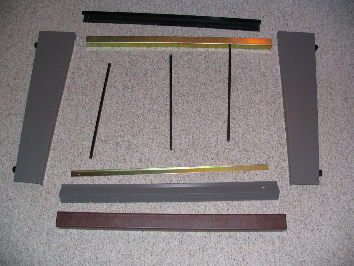
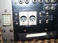
Should have piloted the hole bigger...tried to drill it out...broke one bit and after some more attempts I gave up on that one. As easy as it was to break the screw I was surprised that it was so tough to drill. Thankfully the lower extruded aluminum member doesn't really do much...it is mostly cosmetic, and holds the headphone jack as well. The armrest is a serious structural member though, and the lower piece is attached to that so even with that one screw missing (which will be hidden when the trim panels get put into place) it is still solid.

Here are the parts ready to assemble (less motherboard):
parts.JPG


And here are those parts with the motherboard all put together...several views worth...
assembled.JPG


side%20view.JPG


rear%20view.JPG


bottom%20view.JPG


And here is an "after" detail shot of the power supply connector area contrasted with a "before" shot:
power%20connector%20detail.JPG
 

Attachments

  • mixing%20console%20%286%29.webp
    mixing%20console%20%286%29.webp
    42 KB · Views: 199
Last edited:
How soon I forgot...

What a PITA it is to solder those Hirose PSU connectors...

20 pins, tightly packed.

Got the PSU end of the power umbilical finished tonight. I have all the parts to put together the mixer end of it, though I'm going to wait to do so until I get the PSU back from Ethan since I've got some minor reassignment of connections to do in the PSU, and I figure since I have the luxery of doing so I may as well apply some logic to how those are reassigned.

Power%20Cable%20PSU%20end%20%231.JPG


Power%20Cable%20PSU%20end%20%232.JPG
 
Last edited:
Capped off the marathon...

by pulling the caps off the Studio PCB, since I have all the replacements here on-hand. No issues arose when pulling the caps. It is interesting to note however that the caps are a mix of 85-degree and 105-degree...likely they (Teac) used whatever they had on-hand at the time, but it is uncharacteristic of other pieces of gear of the same era where it seems to be pretty much exclusively 85-degree caps.

Might put the new caps in tomorrow and finish cleaning it up and inspecting. I've already applied DeoxIT to the switches and pots on this card but I will do it one more time and exercise said components.
 
I'll have to call you...

Mr. Finepoint Soldering!:eek:;)
 
Back
Top