Tascam M520 Story...

  • Thread starter Thread starter sweetbeats
  • Start date Start date
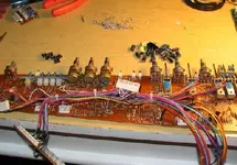
Well, I assembled an umbilical for the power supply. I must say it was a challenging process. The 22AWG cable was very nearly too big to fit through the solder eyelets...plus it is relatively stiff cable. Hemostats were a must.

Got a sort of slide show of the project:

Here are the materials I used to make the cable.
01.JPG


Here is the map I made up of pin assignments for the cable.
02.JPG


The first step was to put a piece of heat-shrink on the end of the cable. For the right-ange connector, the one that will interface with the back of the mixer, I stripped the cable jacket back 1.75", and applied a 1.5" piece of heat-shrink. I left 1.5" of the individual conductors exposed. I like using the 3:1 for this kind of stuff with the glue inside...
03.JPG


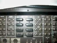
Here is what the inside of the hood looks like...
04.JPG


The first wire...
05.JPG


The first wire complete with little heat-shrink boot...1 down, 19 to go.
06.JPG


Here is a shot about halfway through...
07.JPG


All wires soldered! Time to stuff that hood.
08.JPG


Shot of the hood stuffed and ready for the other half of the hood cover.
09.JPG


Finished right-angle cable end:
10.JPG


This was a terrible thing...I was nearly done with the other end and my flush cutters nicked one of the cables...hench where the solderless connector came in...:o
11.JPG


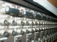
Ahhhhhh...the finished product, and fully tested.
12.JPG
 
Finally finished cleaning all the knob/switch/fader caps

The picture doesn't do it justice...that pile is pretty thick.

I don't wanna clean any more knob/switch/fader caps for awhile.

Clean%20Knob%20Caps.JPG
 
cool pics!
i arrived from holiday (go visit croatia!), and cleaned my m-512 yesterday with faderlube.
everything works perfect now!!!
time to make some beats now....
peace
winz
 
Cory,

Nice work on the PS and the meter lights. And that pile 'o knobs, yikes! I've done that... put them in the dishwasher in a pasta strainer. Pain in the arse!

Now be sure to get a dust cover so you never have to do it again. ;)

I get all my covers from this guy. If he doesn't have what you need on hand he'll custom make anything to your specifications. Nice guy too.

http://www.lecover.com/Cover_Co./Studio/main4a.html

:)
 
I have a complete working M520 for sale complete with PS520 power supply rebuilt by Tascam. Located in east TN. As stated it is complete with stand, wood trim, manual, etc. If anyone might be interested, let me know.
 
David...

M-520 complete with topboard and stand...nice.

This thread gets a few views. Have a price in mind and maybe you want to email me some pics and I'll post them up for you.

I'll Private Message you my email address.
 
Now be sure to get a dust cover so you never have to do it again.

I get all my covers from this guy. If he doesn't have what you need on hand he'll custom make anything to your specifications. Nice guy too.

http://www.lecover.com/Cover_Co./Studio/main4a.html

Tim, thanks for the comments and for the link! I was wondering what to do about a cover. Now I know! I might see what it would cost to have him make a cover that can drop over the 58 while it is racked. Cool! :cool:

BTW, everybody, I actually racked the Power Supply last night, connected up my new umbilical cable, shut my eyes and hit the power switch...All is well! ;)

It is so nice to be able to get the PS-520 off the work table and have it protected in the rack and not teetering behind the mixer with the connector unmounted from the power supply case just to plug in to the mixer. :eek: Plus the power cable from the power supply now reaches protected power.

I'm working up an Excel spreadsheet to log every capacitor. That way I'll be able to manipulate the data to get different lists by single or groups of PCB's to get lists of capacitors as time and budget allow for recapping.

I also cleaned up a couple more of the dress panels last night. They are coming clean really nicely. I use iso alcohol to get label goo off, and then cover the panel with generic window cleaner...rub that around/off really good, do it again and then I'm using an automobile finish by TurtleWax...Finish 2000 or something like that. Anyway it is a liquid polish/protectant and it is further cleaning the panel and giving it a really nice clean lustre. Simply apply with a small cotton cloth rubbing it on, let dry and then wipe off/buff with a towel.

Clean%20Dress%20Panel.JPG
 
M-520 Capacitor List

Here is that M-520 capacitor list I mentioned above...it is in MS Excel format. I should also make it clear that this list ONLY deals with the electrolytics. Basically its got a tab for each PCB that has 1 or more capacitors, and on each tab is a chart with info about the capacitor(s). Then there is a summary tab that collates all the individual PCB tabs so you can get a grand total of each type of capacitor found on the M-520. You can look at just an individual tab if you want to know what caps are found on that PCB, or you can look at the summary chart and know how many of each type of cap if you are doing the whole board, and then there's a color key on the summary chart so you can chase down which PCB's feature which caps if needed.
 
Last edited:
Hi sweatbeats

I have also just bought one of these consoles. I am watching this thread with keen interest. Sweetbeats .... Can I maybe add you on facebook or maybe get your e-mail? Would be great to network with you!

I'll post some comments once I pick up the board on tuesday.

Rick
 
Welcome and congratulations on the M-520 acquisition!

Actually, Private Messaging through the forum is a great way to communicate. I check here more often than my email anyway! :D

Post back the details when you pick up your console. ;)
 
Hm...that was fun...

I'm practicing for de-capping channel cards...took one of my spares and pulled the caps off of it as well as 6 out of the 7 opamps. Went fine, but the traces partially pulled off of about 3 or 4 of the solder pads...I was really careful...its almost like the wafer board is dry or something...like the traces aren't bound well to it...brittle. Anyway, two of the damaged pads are for legs to one of the IC's...so that will be fun to try and figure out...

Nothing better to do so here is a picture of an M-520 Input Amplifier PCB Assembly (E) with no caps and only 1 out of 7 IC's installed.

Blah....blahblah...blah blahblahblah blah.
 

Attachments

  • untitled2.webp
    untitled2.webp
    51.9 KB · Views: 373
Man you are really burning up the midnight oil! looking good though, I've built many umbilicals myself and you did fine work there!


AK
 
I'm practicing for de-capping channel cards...took one of my spares and pulled the caps off of it as well as 6 out of the 7 opamps. Went fine, but the traces partially pulled off of about 3 or 4 of the solder pads...I was really careful...its almost like the wafer board is dry or something...like the traces aren't bound well to it...brittle. Anyway, two of the damaged pads are for legs to one of the IC's...so that will be fun to try and figure out...

Nothing better to do so here is a picture of an M-520 Input Amplifier PCB Assembly (E) with no caps and only 1 out of 7 IC's installed.

Blah....blahblah...blah blahblahblah blah.

That is a phenolic board. It is basically paper and phenolic resin. The copper does not stick as well as you noticed. The boards in your 58's channel cards are glass-epoxy. Much better boards.

--Ethan
 
Huh!

That makes sense...I was actually starting to wonder about that as I'd noticed a difference in the board material. You've explained it well. So, the bottom-line is that on any phenolic board, beeeee careful.
 
cleaning the pots

So sweetbeats,

I've read your entire exploration here. After bringing my tascam home, I've discovered scratchy pots. How has your cleaning worked out? Have the scratchy pots gone away after thurough cleaning? Any more recommendations before I start my own cleaning?

I have also noticed that buss's 2,4,6,8 are not working????
Have you noticed anything in the schematics that links all even buss channels and where they are connected so I may check that connection?
 
rpapa...the best luck I've had cleaning the pots is to get the individual channel cards out of mixer so you can spray deoxit into the body of the pot and then rapidly work the knob shaft back and forth with a shoelace. I'm still having trouble with TRIM knobs. Make sure you stabilize the card when you work on those pots with the shoelace, i.e. load it back into the frame.

So, yeah there are things that sum the odd and even sides of the BUSS MASTER...do this first...can you confirm that this is happening on all channel strips and that the PAN knobs are centered? Where do you here only the odd sides of the stereo buss (i.e. have you checked it on the control room and stereo outs? What about the SOLO function? If you route a channel to busses 1 & 2, SOLO the channel and sweep the PAN knob back forth your source should do the same in the heaadphones...). Just trying to narrow the problem down...

So how does the rest of the board look?
 
Sweetbeats,

The board looks great.

A few problems ...

I've found layer upon layers of glued vinyl at the arm rest. I've had to remove all that junk, which someone had hot glued to the metal underneath. I expected to see a nice wood trim at the arm rest and sides, but the sides have been painted black over some veneered wood. I'm going to construct a nice wood armrest and use the sides as a stencil to make some real wood panels. The meterbridge is flawless. My m-520 does not have the ALPS faders like yours, but has the gold faders with less depth to them. The console came with the original stand, which has about 8 rack spaces built in, perfect to keep the power supply in and more. As I said, nearly all the pots are scratchy and thats a real bummer because I wanted to use it for recording as soon as possible. Anybody know where I can find deoxit in Toronto, Canada?

This is my first summing board, so Sweetbeats I'm a bit of a layman when it comes to this stuff. I'll have to go over the summing section again to narrow down the problem. From what I can tell, something is happening between the channels and the EVEN buss channels. I'll have to report back once I have it hooked up again.
 
Last edited:
On the DeoxIT, I'd contact Caig Laboratories throught their website and find out who is distributing in your area.

Bummer on the trim atrocities on your M-520, but you'll put it right. evm1024 put beautiful new wood trim panels he made on his M-312. Here is the thread...might be an enjoyable read for you. The panels on my M-520 are in pretty good shape...9/10. I'm going to leave them, but we just felled a 100 year old english walnut tree on my property and the wood looks very pretty. Someday I'll probably make new trim panels ala evm1024.

I'm in the midst of replacing the upholstery on the armrest on my M-520. The original vinyl is in decent enough shape, but the factory adhesive isn't holding it on very well anymore, and it is worn enough and an easy enough project I'm just going to go ahead and do it. Plus, IMHO the original material clashes with the dark red cherry finsish of the laminate panels...I set one of the dress panels on my dining room table after cleaning the panel and put up a picture of it a few posts back and I love how the beige goes with the dark cherry finish, so I wanted to find some armrest upholstery that would tie the two together and my wife found some brown material this past weekend that blends with the beige but actually has a mysterious red highlight to it...maybe this week I'll get that on. My focus is to get my M-520 put back together right now...I'll have to make the racapping and switch/pot cleaning a longer term project so I'm going to finish cleaning up the exterior and get it reassembled so I can move it into my tiny control room and out of its current less climate protected shop area since the weather is already starting to turn...don't ever try to move an M-520 with the trim off of it and the modules unmounted...its like jell-o. The whole thing is sort of the equivalent of unit-body automobile construction.

Did your M-520 come with the manual?

What I would suggest to check the buss function is to:
  1. Take channel 4 (because it is the last in the 1 ~ 4 module chain before they connet to the Mother PCB), route it to all groups 1 ~ 8
  2. Make sure that the channel is ON and that the SOLO and PFL switches are out
  3. Raise the BUSS MASTER faders 1 ~ 8 to the shaded section
  4. Depress/latch the MON switch in the MONITOR SELECT switch rack (and make sure it is the only switch latched
  5. Now look up in the monitor mix section (the 16 LEVEL and PAN knob sets above the BUSS MASTER faders)...make sure all source select switches are set to off (center position).
  6. Turn the LEVEL knobs 1 ~ 8 the 12:00 and set the PAN knobs to center
  7. Start your source program material that is connected to input #4
  8. Now, flip the source select switch for monior channel 1 to BUSS, and turn the headphone level knob up to a comfortable level. Do you hear your source connected to channel 4? That's good. :)
  9. Flip the monitor channel 1 source select switch back to center/off. You hear nothing? That is also good...
  10. Repeat the above for monitor channels 2 ~ 8 one at a time.

If the above doesn't work, reapeat all steps with channel 8.

Another suplemental step I'll suggest you do if it doesn't work with channel 8 either is to connect a line-level source to the PGM SUB IN jacks on the back. That is a direct feed to the BUSS MASTER faders and if busses 2,4,6, and 8 don't function their either it will tell us if the problem is truly on the BUSS AMPL. PCB or if it is further upstream.

Let me know how it turns out when you have a chance.
 
"Take channel 4 (because it is the last in the 1 ~ 4 module chain before they connect to the Mother PCB), route it to all groups 1 ~ 8"

Do you mean press all the assign buttons? I think this may be where my downfall is. Is there some kind of routing that has to be done in the back? Right now I have a line into channel 2 that I can hear in pre-fader and solo, however when I try to assign it to a buss, I have no luck.

I tried what you recommended, but I think I may be missing something in the wiring. All I have in terms of wiring is the line-in to channel 2 and my monitors are hooked up to "output master A L & R"

When I picked up the console, there were a series of RCA cables running from the tape-in of channels 1-8 to the FLB 1-8 of the meterbridge. I have left them as they were. Is this correct?

Unfortunately I don't have the manual. I'm an ITB type of guy attempting to go OTB and I have no idea what I'm doing :o

If you could lead me along here that would be great. For some reason I had everything working where I picked it up, but now I can't seem to work it out.

Too bad I can't come and grab that tree from you :)
 
...

Make sure there are jumper plugs installed on each of the (20) channels and each of the (8) Pgm Buss Access Snd/Rcv patch points.
:eek:;)
 

Attachments

  • Im002864a.webp
    Im002864a.webp
    26.7 KB · Views: 321
  • Im002865a.webp
    Im002865a.webp
    25 KB · Views: 317
Back
Top