You are using an out of date browser. It may not display this or other websites correctly.
You should upgrade or use an alternative browser.
You should upgrade or use an alternative browser.
sweetbeats
Reel deep thoughts...
Huh...I don't think so...any way to put up or link a picture of what they look like? I've worked with relays on Tascam r2r amp cards as well as Ampex 440 electronics (bigger cube-type relays on those) and I don't see anything like that on the master section PCB's, but maybe there are and they just don't look like that. I'm suspecting a transistor or transistors at the moment. Definitely green in that area and evm1024 has given me some pointers to get my knowledge a little deeper on those types of components.
gerard
Member
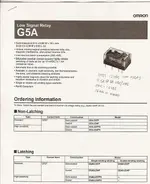
Hey Sweetbeats, not sure if this would be any help to ya but I posted the Mute section on my M3500. Seems it's kinda similar/kinda not to your section. Maybe it would it help. I also posted the Solo relay data sheet of the one used in my board. The relay plugs into a standard DIP socket (like a op amp) and is just a little taller than a op amp. Some have a clear case, some are solid black, it's just a 2 pole switch with a electro magnet that "flips" the switch. I'm not a expert, just know enought to be dangerous! Hope this helps, even just a small bit.
Jerry
Hope this helps, even just a small bit. Jerry
Attachments
sweetbeats
Reel deep thoughts...
Gerard...sorry I never followed up to that last post. No relays in the M-___.
I have done nothing on the non-functioning DIM control or 400Hz oscillator tone issues...kind of dreading both really because I think both problems are over my head. Wish I was like one of those really smart people that can look at a PCB and draw the schematic. I've learned how to do really simple stuff but the M-___ is way beyond my threashhold of "simple".
I did recently receive the replacement resistors for the oscillator, so at some point I'll swap those out and see if maybe there is indeed a bad resistor in there even though they all tested good...maybe one only misbehaves when under load.
If that doesn't work its back to the drawing board.
But in the meantime I DID recap one of the channel modules, and socketed 11 of the opamp positions. I haven't reassembled it yet, but it is all cleaned up (ala M-520 style...i.e. cleaned contacts and strategically cleaned pots and switches, checked and cleaned the boards and wiring). The channel frame, dress panel and all the knob and switch caps are already clean so at this point I just have to put it together. That'll be fun though because then I can do the before and after shot of the clean module next to an untouched module.
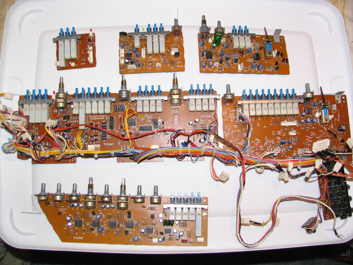
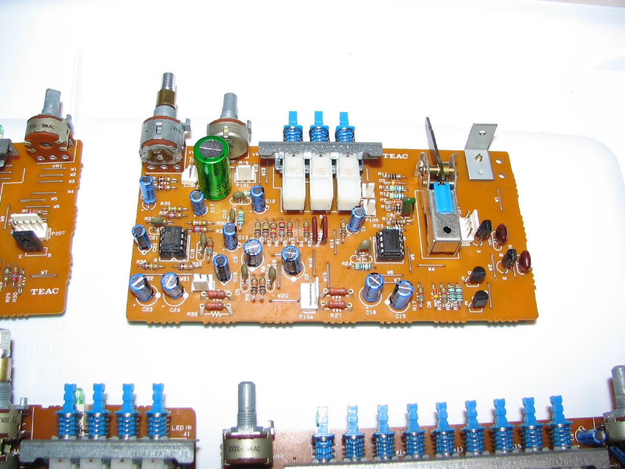
Here are all the PCB's recapped with select socketed opamp upgrades. I socketed the upgraded opamp positions because I possibly want to try some different chips. All upgraded opamps were bypassed with a 0.1uF 100V film cap.
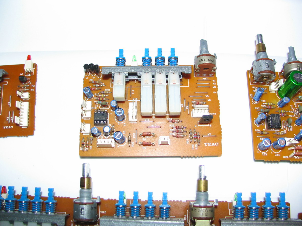
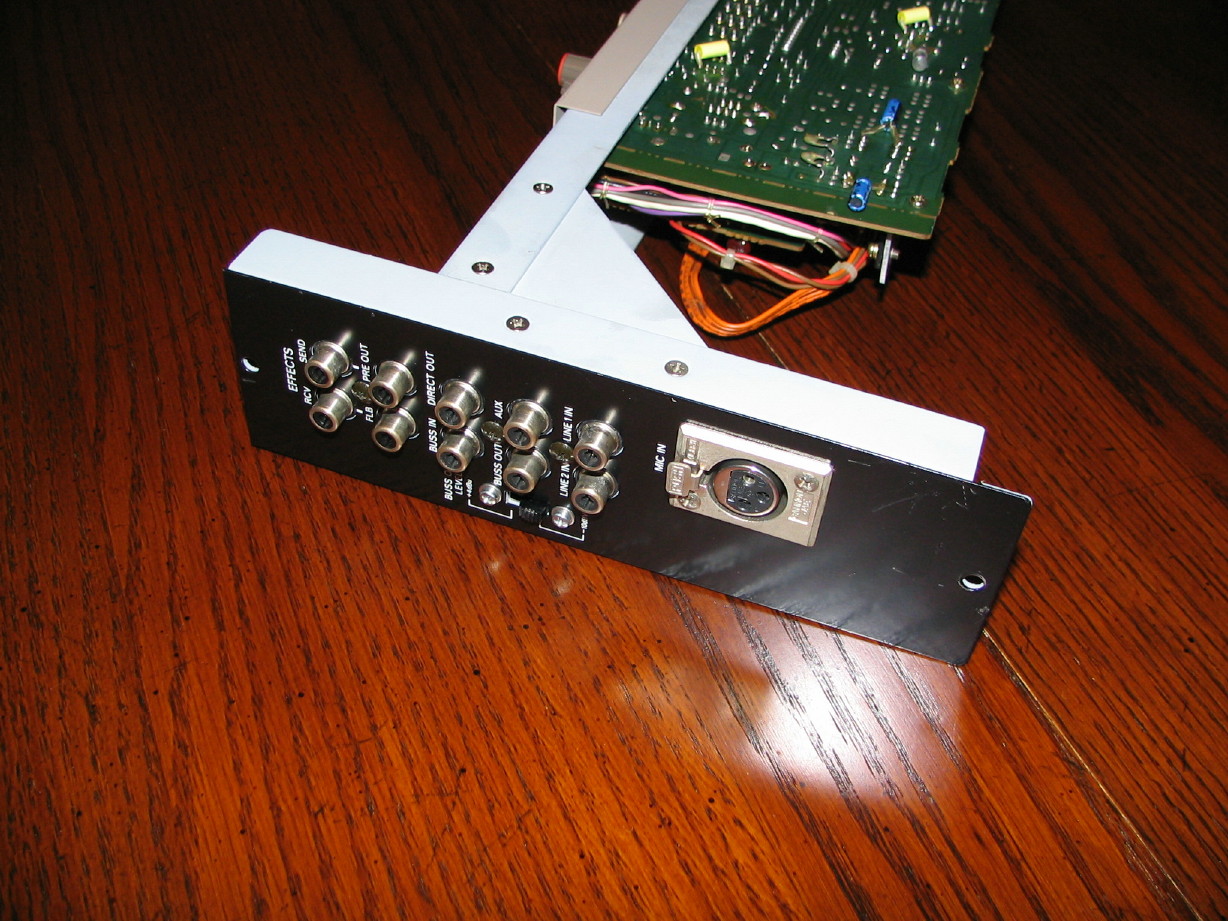
Here is what I'm still calling the "MUTE/SOLO PCB"...wish I had a better name. I'm open to suggestions. It should actually be called something having to do with the stereo buss since it has the stereo pan control on it as well as the driver for the stereo buss and the direct out jack...I installed a TLE2142 chip on this one. I have no experience with them but I purchased a few awhile ago because they were the only thing I could find that could match the output of the 4556 that used to be there. Teac used the 4556's all over in the M-520 in strategic places where higher output was demanded, but it has yet to be answered whether the 70mA drive of the 4556 was overkill or not (i.e. if a chip with less drive would work). Regardless I'll try it. The rest of the specs of the 2142 look pretty good and they were relatively cheap.
Here is what I've called the INPUT B PCB. It has the mic pre and line input drivers on it as well as the input select controls and trims, phase reverse, pad and phantom controls. I put an OPA2134 in for the line input drivers and am gettin' crazy and trying the LME49860 for the mic pre...
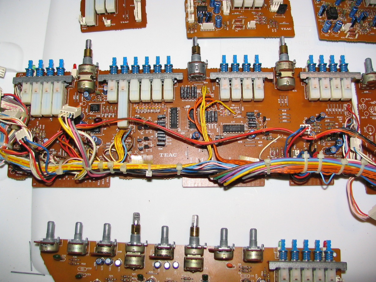
Here is the INPUT A PCB...now you might wonder why I call this one the 'A' card since the one above has the input drivers on it...I'm just following Teac naming convention since there are some wiring labels on the PCB that indicate this one is called "Input" something, and Teac would have called this the primary because all the other cards connect to it...it is the mother channel card and the one with the finger contacts on it to connect the channel to the motherboard. Just a recap on this one...no opamps upgraded. Bunch of logic IC's on this PCB and a couple-three audio drivers but they are for the monitor and aux busses and at this point those are less critical in my mind.
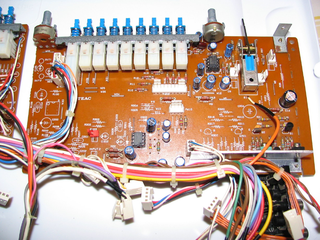
Here is the BUSS PCB, the one with the PGM group routing controls and such on it. Two audio drivers on this one...can't recall what they do but I put one OPA2134 in as well as one LME49860...I'll have to review my notes and recall why I did that... ...I know one of them drives the BUSS OUT jack, but the other one...
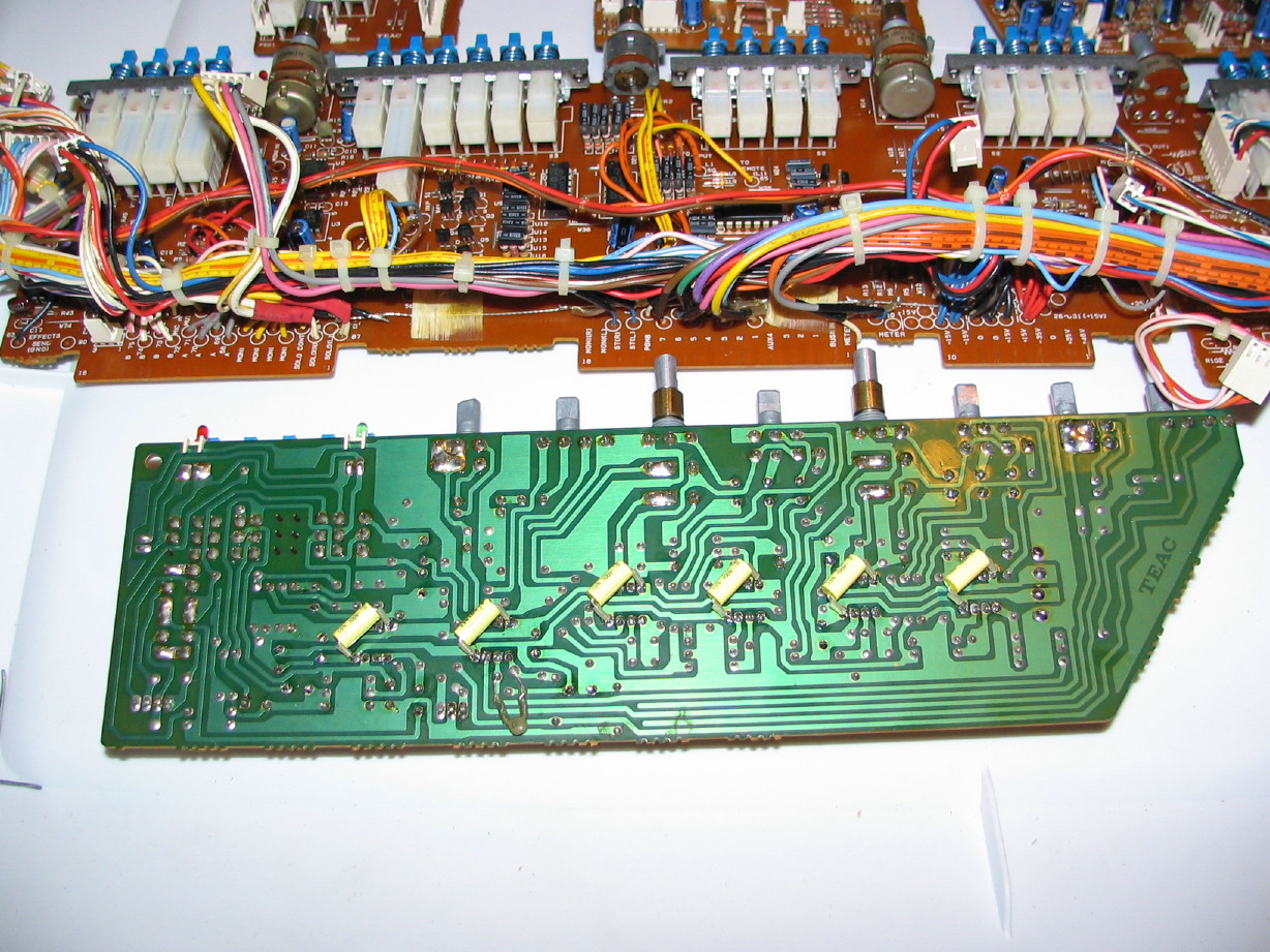
The EQ PCB. Lots of audio IC's on this card...six altogether. I filled them all with OPA2134's. Overkill? Uh-huh...probably. But remember this is one of two channels I'm going to do this to. The rest I'll likely leave stock because my audio tests awhile back took me by suprise in how good the stock channels sounded, but I'm going to build these two "super channels" for mastering and critical sources, so a little decadence is okay right guys? Relatively speaking of course.
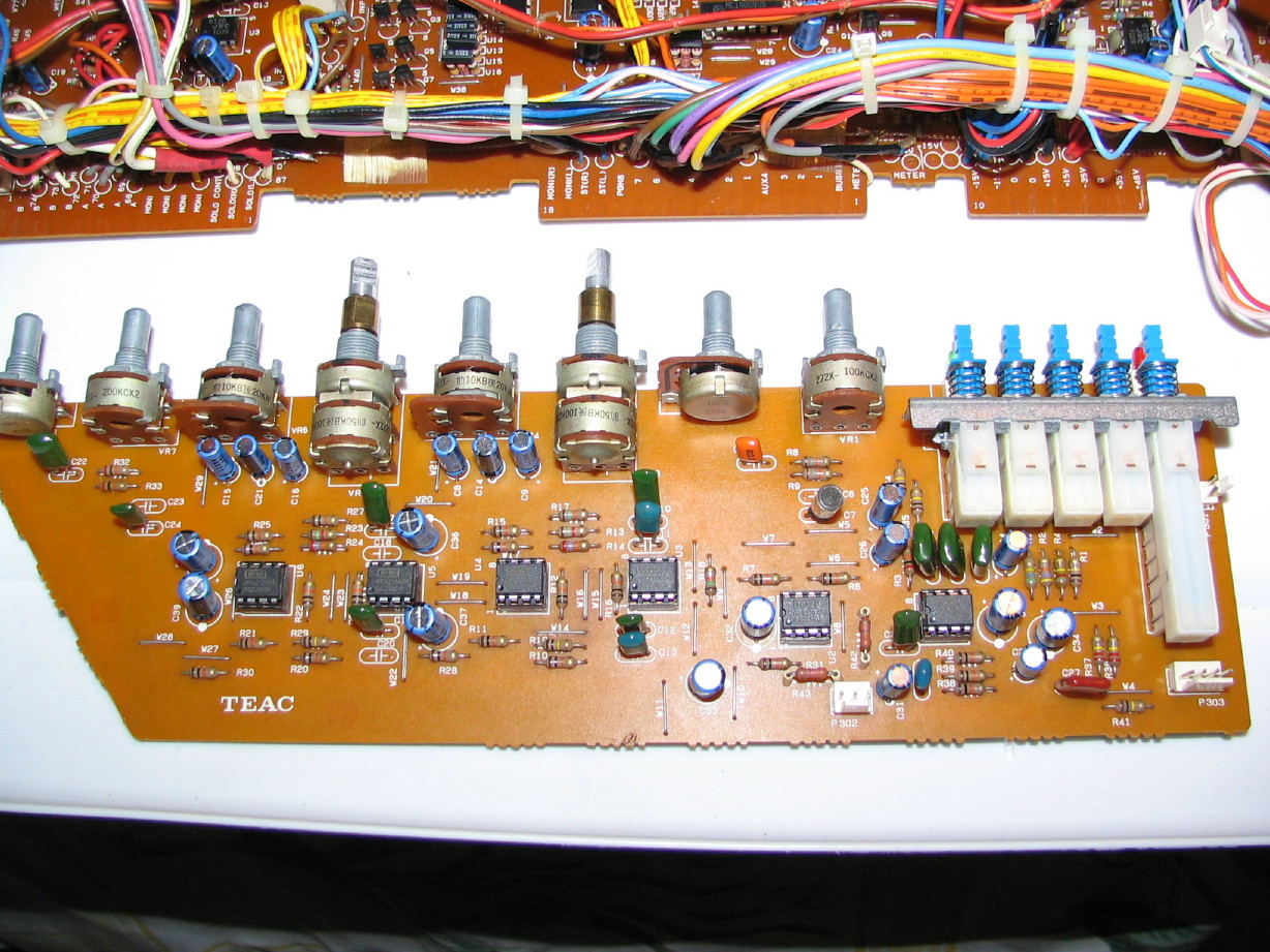
Lastly just a shot of the back of the EQ PCB so you can see the bypass caps.
I have done nothing on the non-functioning DIM control or 400Hz oscillator tone issues...kind of dreading both really because I think both problems are over my head. Wish I was like one of those really smart people that can look at a PCB and draw the schematic. I've learned how to do really simple stuff but the M-___ is way beyond my threashhold of "simple".
I did recently receive the replacement resistors for the oscillator, so at some point I'll swap those out and see if maybe there is indeed a bad resistor in there even though they all tested good...maybe one only misbehaves when under load.
If that doesn't work its back to the drawing board.
But in the meantime I DID recap one of the channel modules, and socketed 11 of the opamp positions. I haven't reassembled it yet, but it is all cleaned up (ala M-520 style...i.e. cleaned contacts and strategically cleaned pots and switches, checked and cleaned the boards and wiring). The channel frame, dress panel and all the knob and switch caps are already clean so at this point I just have to put it together. That'll be fun though because then I can do the before and after shot of the clean module next to an untouched module.
Here are all the PCB's recapped with select socketed opamp upgrades. I socketed the upgraded opamp positions because I possibly want to try some different chips. All upgraded opamps were bypassed with a 0.1uF 100V film cap.
Here is what I'm still calling the "MUTE/SOLO PCB"...wish I had a better name. I'm open to suggestions. It should actually be called something having to do with the stereo buss since it has the stereo pan control on it as well as the driver for the stereo buss and the direct out jack...I installed a TLE2142 chip on this one. I have no experience with them but I purchased a few awhile ago because they were the only thing I could find that could match the output of the 4556 that used to be there. Teac used the 4556's all over in the M-520 in strategic places where higher output was demanded, but it has yet to be answered whether the 70mA drive of the 4556 was overkill or not (i.e. if a chip with less drive would work). Regardless I'll try it. The rest of the specs of the 2142 look pretty good and they were relatively cheap.
Here is what I've called the INPUT B PCB. It has the mic pre and line input drivers on it as well as the input select controls and trims, phase reverse, pad and phantom controls. I put an OPA2134 in for the line input drivers and am gettin' crazy and trying the LME49860 for the mic pre...
Here is the INPUT A PCB...now you might wonder why I call this one the 'A' card since the one above has the input drivers on it...I'm just following Teac naming convention since there are some wiring labels on the PCB that indicate this one is called "Input" something, and Teac would have called this the primary because all the other cards connect to it...it is the mother channel card and the one with the finger contacts on it to connect the channel to the motherboard. Just a recap on this one...no opamps upgraded. Bunch of logic IC's on this PCB and a couple-three audio drivers but they are for the monitor and aux busses and at this point those are less critical in my mind.
Here is the BUSS PCB, the one with the PGM group routing controls and such on it. Two audio drivers on this one...can't recall what they do but I put one OPA2134 in as well as one LME49860...I'll have to review my notes and recall why I did that...
...I know one of them drives the BUSS OUT jack, but the other one...
The EQ PCB. Lots of audio IC's on this card...six altogether. I filled them all with OPA2134's. Overkill? Uh-huh...probably. But remember this is one of two channels I'm going to do this to. The rest I'll likely leave stock because my audio tests awhile back took me by suprise in how good the stock channels sounded, but I'm going to build these two "super channels" for mastering and critical sources, so a little decadence is okay right guys? Relatively speaking of course.
Lastly just a shot of the back of the EQ PCB so you can see the bypass caps.
sweetbeats
Reel deep thoughts...
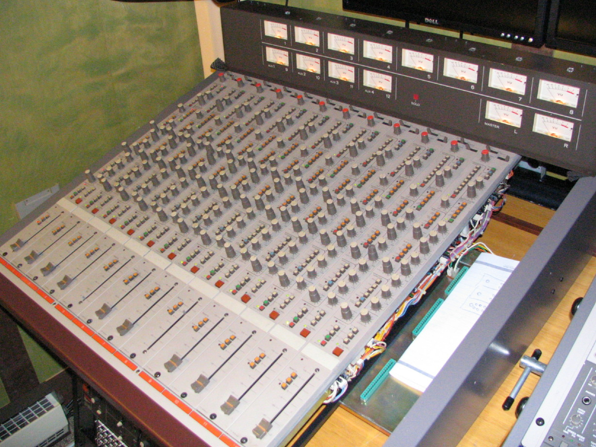
12 Strips In
First time I've ever had all 12 strips installed at once.

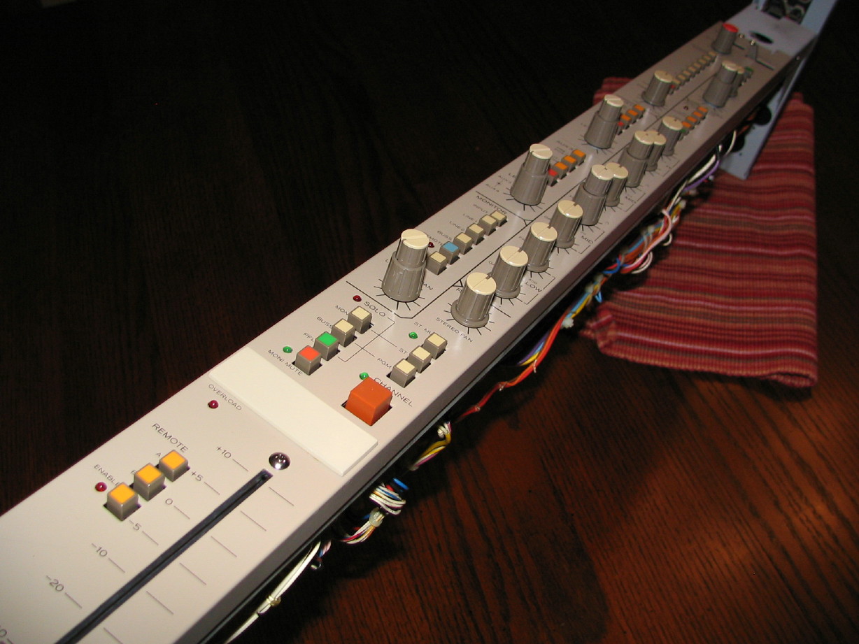
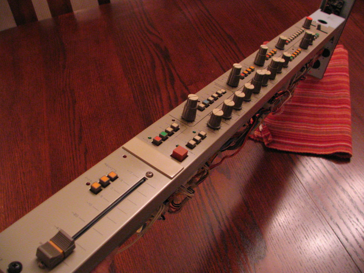
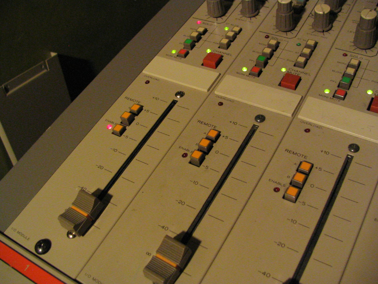
Here are some detail shots of the cleaned-up/recapped/modded channel strip out of the mixer frame:
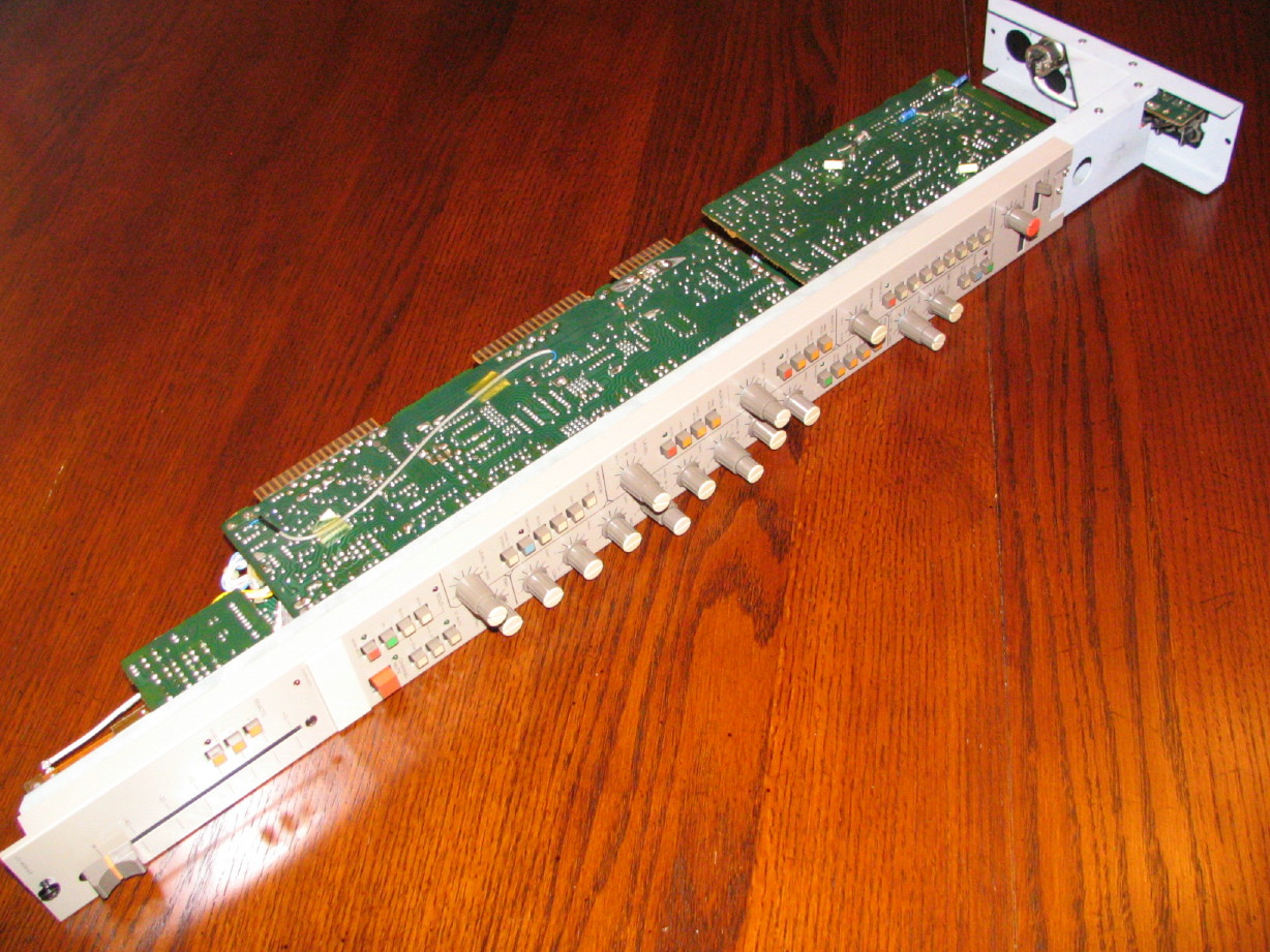
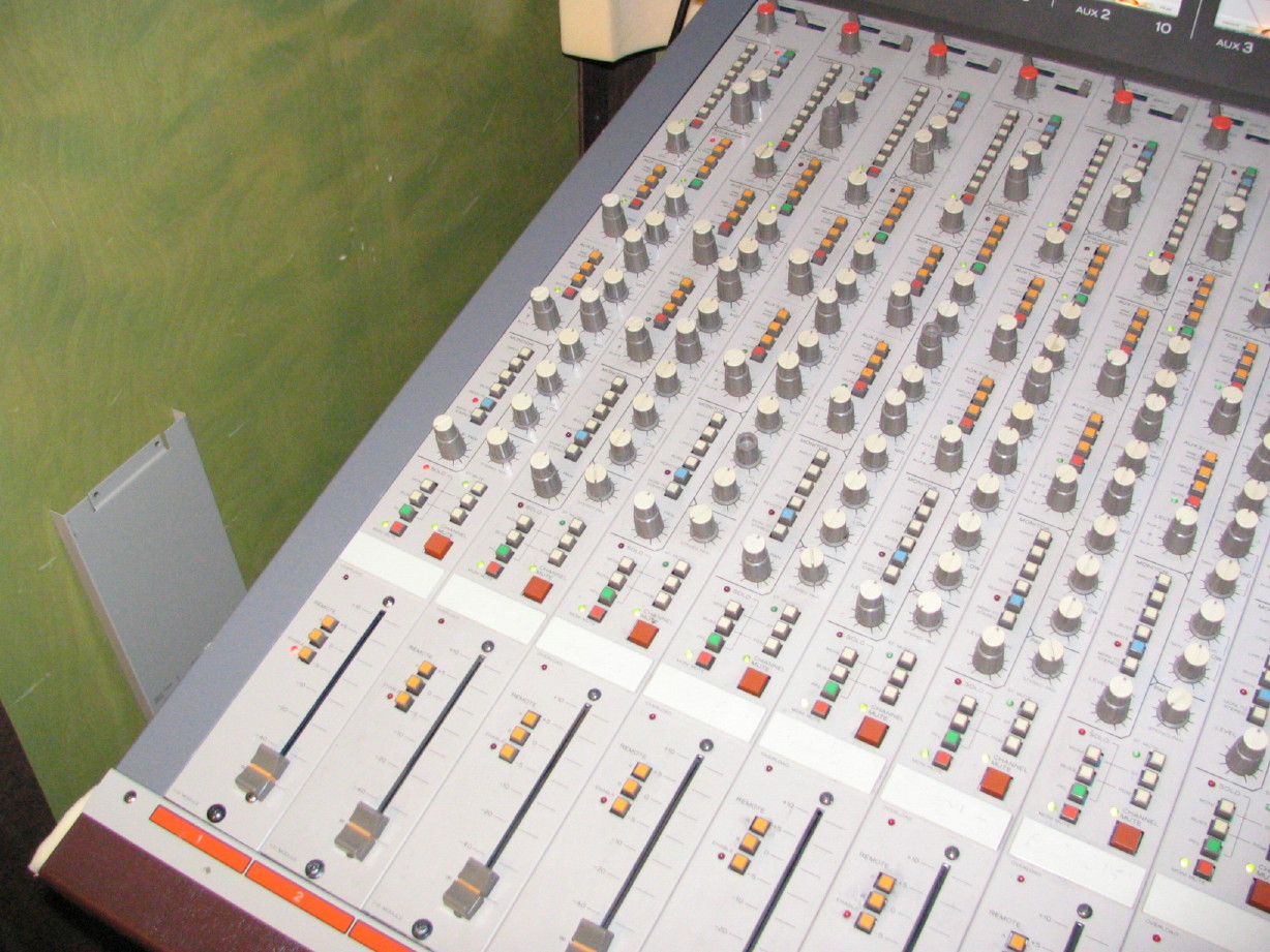
And here is a collection of detail pictures of that same strip in the frame so you can see kind of a before and after...the cleaned up channel strip next to the ones that need cleaning up:
First time I've ever had all 12 strips installed at once.
Here are some detail shots of the cleaned-up/recapped/modded channel strip out of the mixer frame:
And here is a collection of detail pictures of that same strip in the frame so you can see kind of a before and after...the cleaned up channel strip next to the ones that need cleaning up:
cjacek
Analogue Enthusiast
Cory, that is a beautiful piece of work! ")
R
Ritzy
Registered (Ab)User
Wow, fantastic job! The contrast between the pics from page 1 and what the mixer looks like now is amazing. I tip my hat to you, Sir!
This really is an amazing piece; swept high and low EQ plus two fully parametric mid-ranges, the extensive bussing, monitoring and metering options -you can tell Tascam went pretty all out on this one.
One thing that perplexes me a little, especially considering the extensive routing options on this mixer, is the lack of buss group channel strips lke you would find on the M520. I read through this whole thread, but that was a few months back now so I can't remember all the details. It looks to me like the group buss levels are controlled within each channel strip by the "Buss Master" knobs at the top, rather than by faders in a seperate master section. Is that the case? Each strip doubles as a buss master kinda thing?
Regarding dating the board, I can't remember if this was covered in the discussion or not, but op-amp ICs will usually have some sort of date code on them. The pots may or may not have some kind of date code too, as well as, I believe, a lot of electrolytic caps, especially the larger ones.
I'm curious how the Tascam-M___ sounds compared to the 520? I noticed you're selling your 520; I take it you'll be using this as your main console?
Alas, great job!
sweetbeats
Reel deep thoughts...
Thanks, Ritzy! 
Tascam did go all out, and it is easy to see why it never made it to market. I can see how things were value engineered to focus features on more important elements with a marginally greater reduction in production costs. Smart moves and the M-500 mixers are still kick-butt in terms of quality and features for sure, and have some goodies I wish the M-___ had!
Yes, the M-___ is a tru "inline" mixer...input strips and buss mastering on the same strip...advantages and disadvantages depending on how you look at it...strips installed in slots 1 ~ 8 handle PGM Groups 1 ~ 8 respectively, strips in slots 9 ~ 12 handle the AUX 1 ~ 4 masters. Wouldn't mind those being on faders instead of potentiometers, but I can't have it all, and the mixer is pretty deep as it is...coulda put the buss faders next to the channel fader but that could be pretty incovenient and confusing from and engineering and operations standpoint.
Also, I think it was Technoplayer that pointed out the date stamping on the IC's pretty early in the thread...we figure the board is likely dated from mid '81 to late '82 which makes sense because Jimmy in analog support at Teac doesn't recognize the board and he's been there for about 26+ years so it couldn't be later than 82-ish and I don't reckon it could be from earlier than '81 because of the graphics on the control surface and the control knobs and such all correspond with gear in that was instroduced in that era...the M-500 mixers came out in '83 I think and a 2-year R&D period seems about right...
The M-___ is my main board. Both the M-520 and M-___ sound great, but my limited work with the M-___ present a lot more headroom than the M-520 (not that the M-520 is limited or bad...I was just shocked by the M-___).
M
Muckelroy
Member
Cory,
I am still flabbergasted by the quantity and quality of work you have put into this mixer, and want to re-congratulate you for an outstanding beauty of a board you've got there.
Having behemoth vintage electronics in a household always make great conversation pieces. But there's something special to be said about conversation pieces that are functional, and rival modern-day equipment that does the same functions.
Calling this mixer a "conversation piece" is a gross understatement. You've got what's obviously an obscure prototype model mixer that the manufacturer seems to have no knowledge or documentation of as far as we can see. The original state of the mixer was such that it was covered in rust, and rodent excrement, and did not have a power supply.
Let's not forget that the mixer was originally located some (what was it?...) thousand miles plus from him. He drove all the way to the location of this mixer himself, and transported it to his home town. He then not only painstakingly cleaned up every hardware and electronic component of this mixer, but repaired and enhanced the hardware with upgrades.
He even retrofitted an M-520 power supply to work with this console. Now, that in itself is enough of a task worthy of a senior level project for someone working on an electronics engineering degree!
Well done, my friend. Just re-summarizing this post was enjoyable")
I am still flabbergasted by the quantity and quality of work you have put into this mixer, and want to re-congratulate you for an outstanding beauty of a board you've got there.
Having behemoth vintage electronics in a household always make great conversation pieces. But there's something special to be said about conversation pieces that are functional, and rival modern-day equipment that does the same functions.
Calling this mixer a "conversation piece" is a gross understatement. You've got what's obviously an obscure prototype model mixer that the manufacturer seems to have no knowledge or documentation of as far as we can see. The original state of the mixer was such that it was covered in rust, and rodent excrement, and did not have a power supply.
Let's not forget that the mixer was originally located some (what was it?...) thousand miles plus from him. He drove all the way to the location of this mixer himself, and transported it to his home town. He then not only painstakingly cleaned up every hardware and electronic component of this mixer, but repaired and enhanced the hardware with upgrades.
He even retrofitted an M-520 power supply to work with this console. Now, that in itself is enough of a task worthy of a senior level project for someone working on an electronics engineering degree!
Well done, my friend. Just re-summarizing this post was enjoyable
sweetbeats
Reel deep thoughts...
Shoot! The oscillator issue gets worse
Hopefully the worsening of the condition might point the way to the culprit but I need help.
I replaced all the resistors associated with the test tone generator last night. Now it isn't just the 400Hz tone that dies, it is now the 64Hz, 400Hz and 1kHz tones that die. 6.4kHz and 12kHz tones are okay still.
Hope somebody can help...pleez...
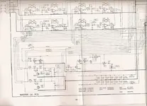
Here is a jpeg of the Talkback PCB on the M-520 mixer. I believe the oscillator circuitry on the M-___ is similar...maybe it can help somebody help me...
Muck, thanks for the props...I'm definitely fortunate to have it and that goes back to shoulderpain for his generosity in making it available. He found it and made it possible to land in my home.
Hopefully the worsening of the condition might point the way to the culprit but I need help.
I replaced all the resistors associated with the test tone generator last night. Now it isn't just the 400Hz tone that dies, it is now the 64Hz, 400Hz and 1kHz tones that die. 6.4kHz and 12kHz tones are okay still.
- I used good quality metal film resistors.
- I closely inspected the traces and everything looks great.
- Again, the frequency selector switch has been disassembled, inspected, reassembled and tested. It was in beautiful shape inside. I don't believe it to be the switch.
- It has to be something else. A bad cap was mentioned sometime back as the possible cause, but all the caps are new.
- Ideas anybody? The oscillator is driven by a TL072 and I've though about just replacing that to see...
- wondering about resistors in the feedback loop...maybe they're bad?
- Could pull the opamp and then test the feedback resistors...
- Lower frequencies utilize the lower resistance resistors of the ones I replaced. That means more current, and maybe that's taxing whatever it is that's going south?
- It seems current is involved in the issue since some tones work and some don't...
Hope somebody can help...pleez...
Here is a jpeg of the Talkback PCB on the M-520 mixer. I believe the oscillator circuitry on the M-___ is similar...maybe it can help somebody help me...
Muck, thanks for the props...I'm definitely fortunate to have it and that goes back to shoulderpain for his generosity in making it available. He found it and made it possible to land in my home.
sweetbeats
Reel deep thoughts...
Frame fully loaded for the first time since I've had it...
Nothing blew up.

Nothing blew up.
cjacek
Analogue Enthusiast
Absolutely beautiful!
Guys, help Cory out with the oscillator issue!
Guys, help Cory out with the oscillator issue!
sweetbeats
Reel deep thoughts...
Just to be clear...
I don't want more credit than what is actually due...Only the frame, one channel and the master section have been cleaned up, and the repairs and upgrades (particularly the power supply) came with a lot of Analog Only help, especially from Ethan (evm1024).
I've got a long ways to go, but without the AO Forum it'd still just be this:

Let's not forget that the mixer was originally located some (what was it?...) thousand miles plus from him. He drove all the way to the location of this mixer himself, and transported it to his home town. He then not only painstakingly cleaned up every hardware and electronic component of this mixer, but repaired and enhanced the hardware with upgrades.
He even retrofitted an M-520 power supply to work with this console. Now, that in itself is enough of a task worthy of a senior level project for someone working on an electronics engineering degree!
I don't want more credit than what is actually due...Only the frame, one channel and the master section have been cleaned up, and the repairs and upgrades (particularly the power supply) came with a lot of Analog Only help, especially from Ethan (evm1024).
I've got a long ways to go, but without the AO Forum it'd still just be this:
lo.fi.love
Functionally obsessed.
Quick question: I've been following this thread for a while now, and it's exciting to see the progress. It makes me wish that I knew more about electronics. What should I do to start? Specifically, I would like to know enough to understand capacitor upgrades and maybe IC upgrades for mixers and such.
I want to take Intro to Electrical Engineering at the local community college, but I'll have to get the math and physics prerequisites out of the way first.
I want to take Intro to Electrical Engineering at the local community college, but I'll have to get the math and physics prerequisites out of the way first.
sweetbeats
Reel deep thoughts...
I'm not really qualified to give more than a 'my 2p' answer because I'm not standing far from where you are in terms of knowledge and understanding.
My 2p? I've learned what I know from guys on this forum and elsewhere just simply as a result of working through fixin' stuff. Its taken a lot of reading of articles forwarded or linked, a lot of time staring at PCB'S and schematics in frustration, and most importantly it has taken kind mentoring and time from some helpful people and I don't take that for granted.
With capacitors I make it the rule in accordance with others to replace using 105 degree caps. I like the Nichicon caps because they seem well-made, have a good reputation, are reasonably priced, and even have some lines specified for audio FWIW. Not certain if there is any benefit to that. I use their PW caps for PSU and non-audio applications and I use the KT series for audio. I also use the VZ caps for non-audio if I can't find the right values in a PW. I seem to see Panasonic mentioned as well. I believe these to be well-made as well...A little pricier. I'm sure there are others.
It SEEMS like, in general, caps are adequately sized in the Tascam gear...I haven't run across information indicating that 'such-and-such cap is way undersized and needs to be upgraded NOW' with the Tascam stuff like I have with the Ampex 440. In the case of the 440 it has been important to be involved in the Ampex List and connect with a few benevolent souls over there helping with that...mentoring me. Would it be nice to be able to identify upgrades on my own? Sure, but it would take so much time to gain that knowledge, and I've spent so much time tinkering that I'm pretty comfortable taking somebody's word for it, particularly if I know and trust them.
Case in point: am I happy evm1024 has an MS-16 that uses the same amp cards as my 58? You bet. I'm going to follow what he did closely, and try and learn and understand why so I can decide if it is right for me...but I know and trust that he did the research, has the knowledge and experience to doing/testing/evaluating such changes.
Some caps can benfit form being upsized, others like in logic circuits effect timing and are a specific capacitance for that reason. There's a lot to it, but I've sort settled on figuring that, for equipment that has at least SOME sort following (or at least a famly of equipment), there will be some knowns about what is good to change and what is good to go with stock values. I figure if that leaves a problem or some dissatisfaction then I can go fishing. For me the best education has been to get in and do and ask specifics along the way. Start with a small project, like recapping your PS-520. you can get the Nichicon PW's readily from number of sources. Mouser has been my favorite. There is a cap in that PSU that*may* be a diffent value than what is on the schematic and it is preferable just to go with what they installed at the factory. I can get you specifics if desired.
Big picture? about a year ago I knew pretty much nothing about what caps do and how to identify what's needed and how to source them...didn't even know there was a right and wrong way to put (polar) caps in...had no experience pulling them and installing new. Anybody can do it. Just do it in moderation. I'm over the top, but your PS-520 would be great starter project and I can walk you through that. May be a good topic for my M-520 Story thread or start your own specific to recapping the PS-520 and I'll jump in.
Opamps. You opened it, dude. There are specific 'safe' upgrades and more that are less known for which it is helpful to have a scope to diagnose oscillation, or as a general rule (if it isn't bypassed already) is to put a small film bypass cap on the +V and -V inputs to the IC. I can walk you through that too thanks to dementedchord and evm1024. There is a thread buried in the DIY forum about M-512 M-520 upgrades. Good info in there. You might just want to look that over as it leaves specific questions as to what type of chip can/could be used for the different applications in the M-500 boards, but most importantly I think you need to ask what the purpose of the upgrade is...why to do it. An opamp upgrade *may* result in lower noise, distortion and more accurate tracking of the amp chip, = cleaner more accurate sound/better dynamic tracking. Some or all of that may get buried in the rest of the signal path okay? And done wrong/select the wrong chip for the app and it will sound worse than what you had. An opamp doesn't live on an island. It is a citizen with other components with which it is associated. As it came from the factory those components lived in harmony (hopefully) by design. Put a new opamp in there and they may still live in harmony, maybe even more zealous exuberant harmony, or the rest of the community may have a hard time keeping up or may be at odds with the new neighbor. That's where the scope comes in, and there are always ways to deal with it, but there are trade-offs in everything you do...compromises...the rabbit hole goes deep. You can't expect or shouldn't expect to throw a faster chip in there and be blown away. Then again there is always the potential of a pleasing outcome. Jeff, you loved your M-30 right? Liked how it sounded? That's the result of harmony. Get used to the M-520 and see what you think. I put a bunch of new chips in channel 1 on the M-___ right? Jury is still out. I'm not sure I actually like it as well as the stock confiuration which is one reason I socketed the IC's I upgraded so I could easily switch back or try others. Have to do some A/B testing soon, track it and put samples up here.
So those are some things to consider. Teac, along with plenty others made liberal use of the TL072...A tried and true workhorse. A good safe upgrade for the 072 is the OPA2134. The three things to consider are why do it, can your PSU handle it, and what if anything needs to change in the 'neighborhood' (good insurance to add that film cap between pins 4 and 8 of the IC...you can see that in the picture a few posts back of the solder side of the the EQ PCB...the little yellow things).
Hope that helps in some way. Okay...that was 3p.
lo.fi.love
Functionally obsessed.
Hope that helps in some way. Okay...that was 3p.
That definitely helps... and thank you for taking the time to write it all out. I was specifically seeking your opinion, since you began with basically the same amount of knowledge that I have now. I have a vague understanding of what different electronics components do, but I've never taken the time to investigate things further.
I'm saving your reply so I can come back to it later. I've got a couple big projects going on right now, including redesigning my entire setup to accommodate my M-520. It's still on its side on my bedroom floor
sweetbeats
Reel deep thoughts...
evm1024 has been assisting with the oscillator issue. No solution yet, but I took the time to draw up a schematic for the oscillator circuit...there were some similarities to the M-500 oscillator so I got out the whilte-out and modified it to fit the M-___. So at present Ethan took the time look over the schematic, describe the operation of the circuit and suggest some troubleshooting. Haven't gotten to that yet because I have also been working on the headphone amp which has, as of just recently, become really, really noisy. So here's a related thread in the DIY forum on that issue:
https://homerecording.com/bbs/showthread.php?p=3166188#post3166188
BTW, here is a link to the oscillator schematic:
https://www.torridheatstudios.com/ftp/share/Documentation/Tascam/Tascam%20M-___/Tascam%20M-___%20Oscillator%20Schematic%20v2009_06_19.jpg
Anyway, thanks again to Ethan for his time and talent.")
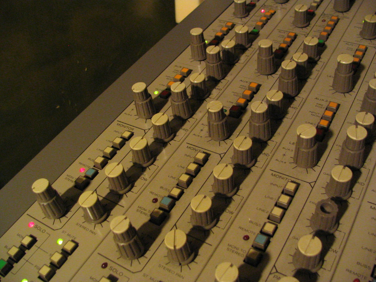
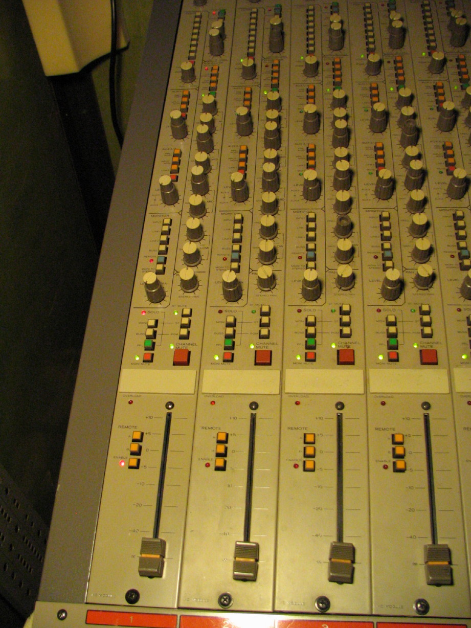
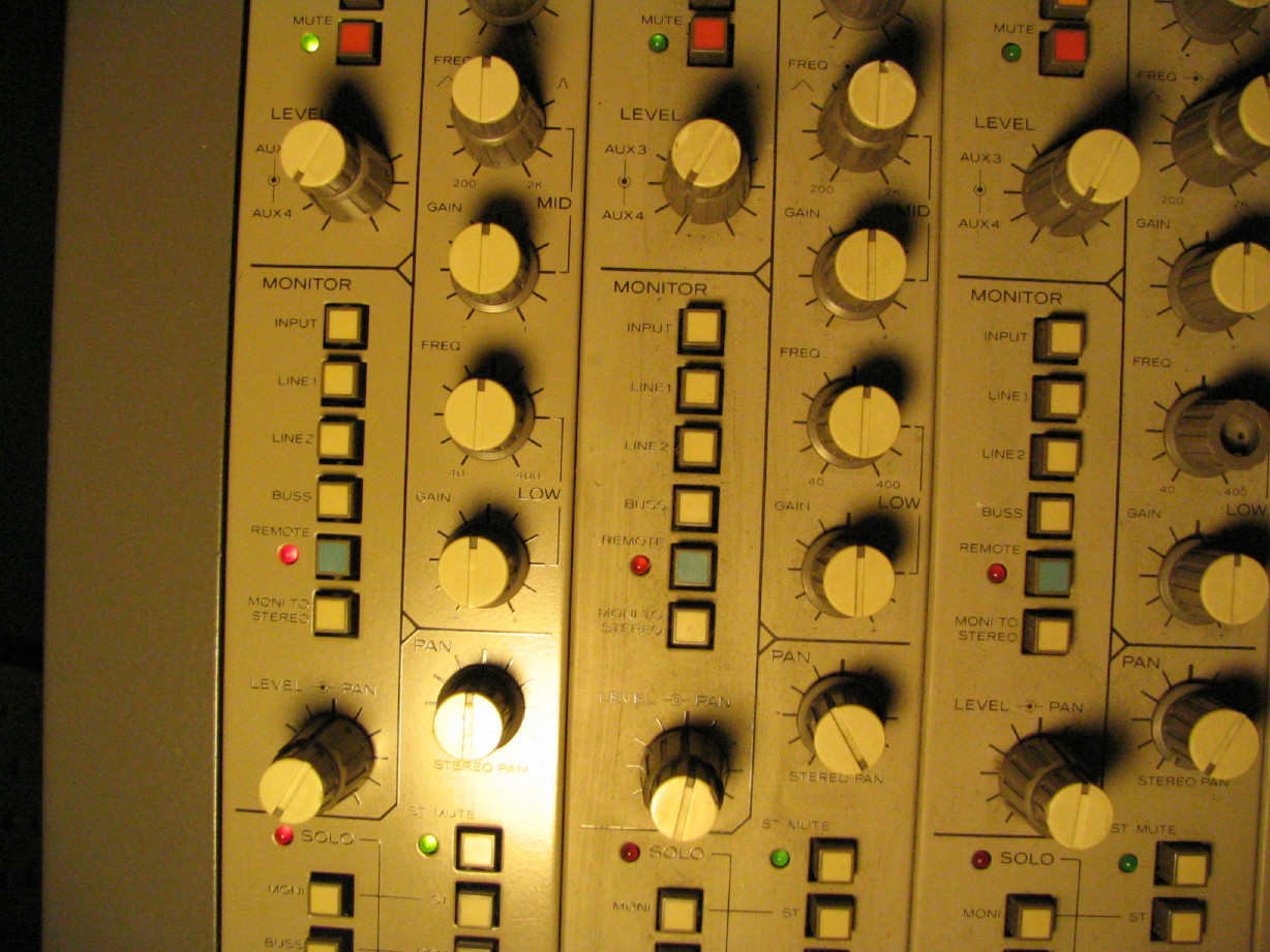
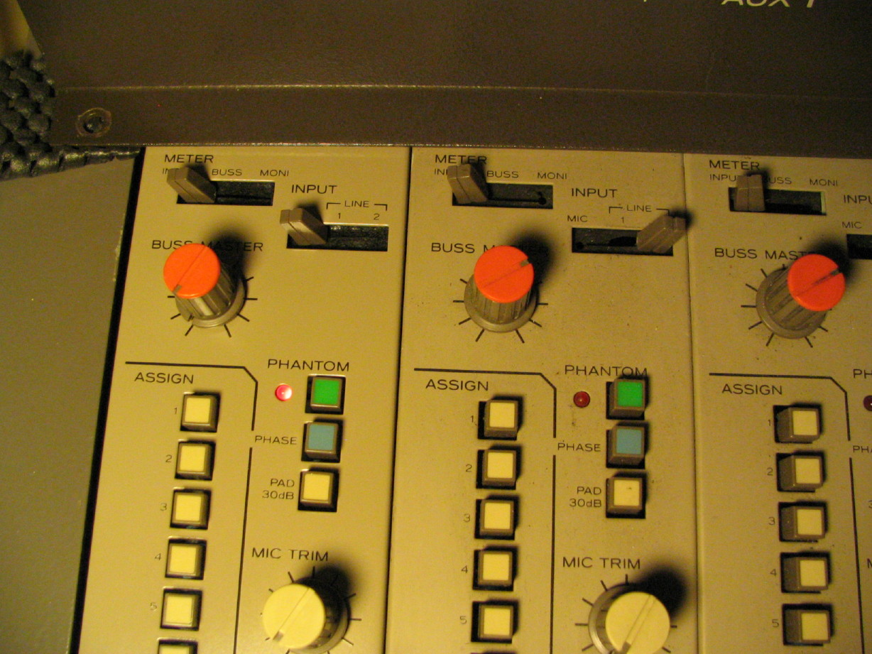
The other thing I've been working on is reconfiguring the switch caps...The color scheme has never made much sense to me, save for a couple obvious bits. I was able to move colors around and do soome swapping of switch caps in the master section so that it makes a lot more sense to me. My logic, when possible, was aligned with Teac's choices for colors with the M-300 and M-500 mixers. Orange generally means "source". The putty colored caps generally mean "route". I used the green caps for anything monitor buss related. Red caps are always "mute", with the exception of the ST MUTE which is directly above the master channel mute kill switch...I didn't have enough red caps to make those red and I chose orange for those which, in my mind, I'm comfortable with because it creates a visual distinction between the ST MUTE and the CHANNEL MUTE. I also broke logic and used orange for the P48 enable switch. Did that so I had enough putty colored ones for all the routing switches in the master section for the "ECHO RETURN 1 & 2" switchracks...there is some logic to go with using orange though since, when latched, you are "sourcing" the phantom power. :rolleyes:") Anyway, it creates a little visual breakup between the phantom switch, phase reverse and -30dB pad swtich. The last color, blue, gets reserved for oddball stuff. Used it for the PFL switch which is a distinctive function as well as the REMOTE ENABLE switch. I carried the same logic over to the master section too. I'm leaving all the channel knob caps putty colored (except for the buss master knobs which are red...that's cool by me), but I'm going to add some color to the master section knobs. This does two things: 1. it makes more putty knob caps available to replace missing or damaged knob caps on the channel strips, and 2. it presents visual distinction between the channel strips and the master section. Lots of unique, important functions that go on in the master section and I thought it'd be good to have color visual locators for key functions. Here's a shot of some of the strips with the new configuration:
Anyway, it creates a little visual breakup between the phantom switch, phase reverse and -30dB pad swtich. The last color, blue, gets reserved for oddball stuff. Used it for the PFL switch which is a distinctive function as well as the REMOTE ENABLE switch. I carried the same logic over to the master section too. I'm leaving all the channel knob caps putty colored (except for the buss master knobs which are red...that's cool by me), but I'm going to add some color to the master section knobs. This does two things: 1. it makes more putty knob caps available to replace missing or damaged knob caps on the channel strips, and 2. it presents visual distinction between the channel strips and the master section. Lots of unique, important functions that go on in the master section and I thought it'd be good to have color visual locators for key functions. Here's a shot of some of the strips with the new configuration:

https://homerecording.com/bbs/showthread.php?p=3166188#post3166188
BTW, here is a link to the oscillator schematic:
https://www.torridheatstudios.com/ftp/share/Documentation/Tascam/Tascam%20M-___/Tascam%20M-___%20Oscillator%20Schematic%20v2009_06_19.jpg
Anyway, thanks again to Ethan for his time and talent.
The other thing I've been working on is reconfiguring the switch caps...The color scheme has never made much sense to me, save for a couple obvious bits. I was able to move colors around and do soome swapping of switch caps in the master section so that it makes a lot more sense to me. My logic, when possible, was aligned with Teac's choices for colors with the M-300 and M-500 mixers. Orange generally means "source". The putty colored caps generally mean "route". I used the green caps for anything monitor buss related. Red caps are always "mute", with the exception of the ST MUTE which is directly above the master channel mute kill switch...I didn't have enough red caps to make those red and I chose orange for those which, in my mind, I'm comfortable with because it creates a visual distinction between the ST MUTE and the CHANNEL MUTE. I also broke logic and used orange for the P48 enable switch. Did that so I had enough putty colored ones for all the routing switches in the master section for the "ECHO RETURN 1 & 2" switchracks...there is some logic to go with using orange though since, when latched, you are "sourcing" the phantom power.
Anyway, it creates a little visual breakup between the phantom switch, phase reverse and -30dB pad swtich. The last color, blue, gets reserved for oddball stuff. Used it for the PFL switch which is a distinctive function as well as the REMOTE ENABLE switch. I carried the same logic over to the master section too. I'm leaving all the channel knob caps putty colored (except for the buss master knobs which are red...that's cool by me), but I'm going to add some color to the master section knobs. This does two things: 1. it makes more putty knob caps available to replace missing or damaged knob caps on the channel strips, and 2. it presents visual distinction between the channel strips and the master section. Lots of unique, important functions that go on in the master section and I thought it'd be good to have color visual locators for key functions. Here's a shot of some of the strips with the new configuration:
Last edited:
evm1024
New member
Oscillator working
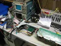
Sweetbeats tone generator uses a quadrature oscillator. I had it on my bench and found time to spend with it the other night. It was throwing a curve in that one of the parts I suspected (C3, 4.7 nF) tested OK in my multimeter. In the end I just went ahead and replaced it and that took care of the problem.
Here is a photo of it generating a 61 Hz sine wave.
--ethan
Attachments
cjacek
Analogue Enthusiast
Ethan's the man!
This deserves more rep points and more!
This deserves more rep points and more!
sweetbeats
Reel deep thoughts...
This deserves more rep points and more!
+70 x 7 to that!
Thank you Ethan!
It was a really good excercise to draw the schematic and learn something about how this section works, but ultimately it is clearly Ethan's victory and my gain. PHEW!
Its wierd seeing pictures of my stuff on somebody else's workbench...heeheehee.
Seriously, just for the sake of it please add to Ethan's reputation if you don't have to "spread it around" more first (like me). He has given a lot of his expertise to the community on this board particularly on this forum and over on the DIY forum.
Let it not be forgotten that the M-___ mixer would not be in its present operational state today without Ethan's help...I think its safe to say that it would still be without a power source without his help!
Similar threads
- Replies
- 4
- Views
- 1K
S
B
- Replies
- 4
- Views
- 625
- Replies
- 168
- Views
- 45K
- Replies
- 11
- Views
- 5K
S