I'm stoked...
Okay...more questions answered last night...more detail later...one teaser though: each channel strip can also function as a
line level stereo channel...isn't that crazy? Its a little funky how you have to do it but because you can source the channel strip to either of the line inputs (LINE1 or LINE2), and you can
also independently source the MONI section on that strip to either LINE1 or LINE2, you can source the strip to one, and the MONI section to the other, pan the strip hard one way, and pan the MONI section hard the other, and then using the "MONI TO STEREO" switch dump the source of the MONI section to the STEREO buss along with the source of the strip. The MONI TO STEREO switch dumps the MONI section into the STEREO buss post fader, pan and mute so the channel strip controls don't effect the panning and level of the MONI section that has been dumped into the STEREO buss...true stereo line mixing out of one channel strip. The funky part is that this only works for routing to the STEREO buss, the eq section can only effect the channel strip source -OR- the MONI section, and the MONI level is on a rotary pot and of course the channel strip level is on a slide fader. BUT...its still cool. This would make it possible to return 4 stereo effects units into the mix when mixing down to 2-track from 8-track for instance as the STEREO buss is the natural buss to send to the mixdown deck, channels 1 ~ 8 would be returns from the 8-track, channels 9 ~ 12 would be stereo effects returns, and then auxes 1 ~ 4 could be used as effects sends. I don't have a need to return 4 stereo effects units...I'm just stating a real-world scenario.
There's more of course, but that is just about the coolest discovery. The nearest competitor in coolness is the whole REMOTE bussing. I've got that totally figured out. More later...
All of this is
completely pointless if only half the STEREO buss works though, but I did some dinking around last night. At first it was depressing because not only was the right channel still down in the STEREO buss, but now there was no PFL coming through, and the stereo SOLO buss was missing a channel too (the
left)...plus things were now panning backwards (i.e. with the right channel down in the STEREO buss you'd expect that if you panned a channel right you'd hear nothing...well, it was passing signal when panned right, and not left). It was making me dizzy. I was starting to feel like things were sort of coming apart.
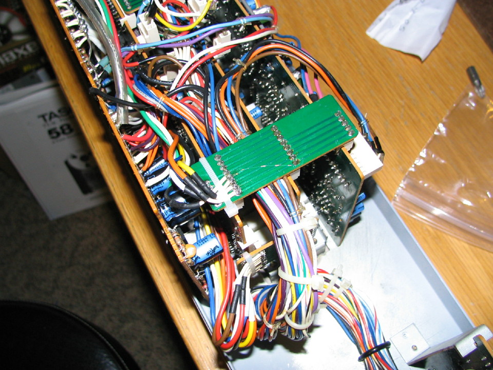
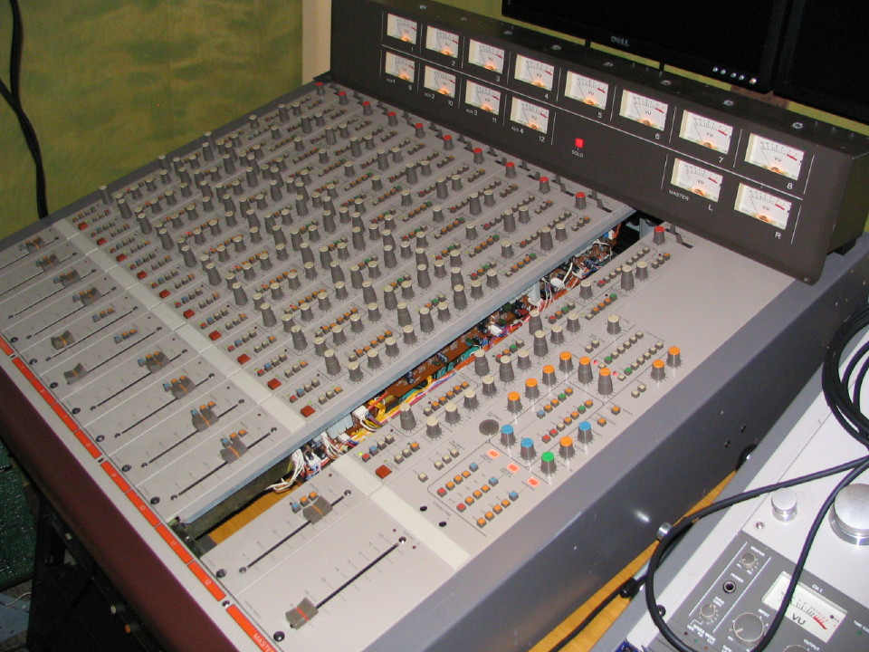
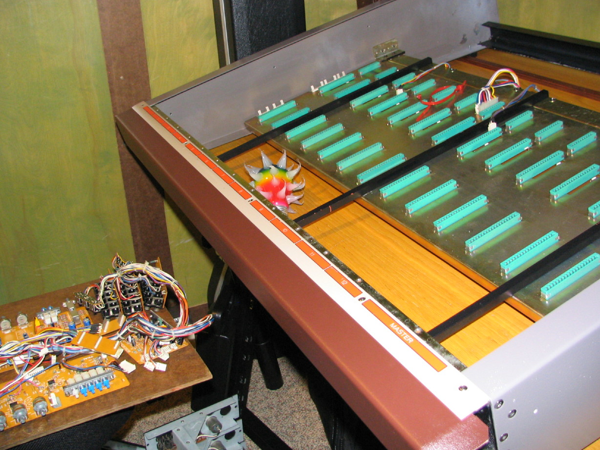
I pulled the master section to look at it some more and reseat connections...I didn't want to take it all apart...it makes me a little nervous because some of the connections are definitely fragile (case in point one more wire came loose from one of the little bridge PCB's that goes between two of the section PCB's...I'll have to repair that...ultimately I need to just replace all 10 wires that go to that little bridge PCB but I'm being lazy...). I was totally figuring that I'd need to tear it all apart again though...figured it was a failed component in the master section and not connections from the channel strips to the master section through the motherboard because I had tested the motherboard and it was good.
Well, I couldn't see anything obvious in looking at the master section except of course for the new loose wire. I decided to call it a night and put the module back in the frame and turned it on because I wanted to see if the bad right channel issue existed in all outputs as well, or just the headphones. So
I was getting signal out of both channels from the CONTROL ROOM, STUDIO, and STEREO outs when sourced to the STEREO buss...things were even panning correctly. There was a
terrible hum though...turned out to be my Behringer headphone amp...that thing has been trouble unfortunately...anyway, so output on both channels nice and clean. SOLO buss was still only one side though, but the PFL worked (only one channel...its mono but of course outputs to both channels). So now I was thinking that both the headphone amp was a problem and something with the connections in the SOLO buss globally. Then I realized that the master meters were
both deflecting with signal whereas before only the left channel deflected reflecting the bad STEREO buss issue. I plugged into the headphone jack on the M-__ and the setereo performance matched what I experienced at the various output jacks. SO...something was now working that was not before, and it was not a headphone amp problem. I stopped there for the night. Thinking about it I was both encouraged and discouraged. I was thinking that
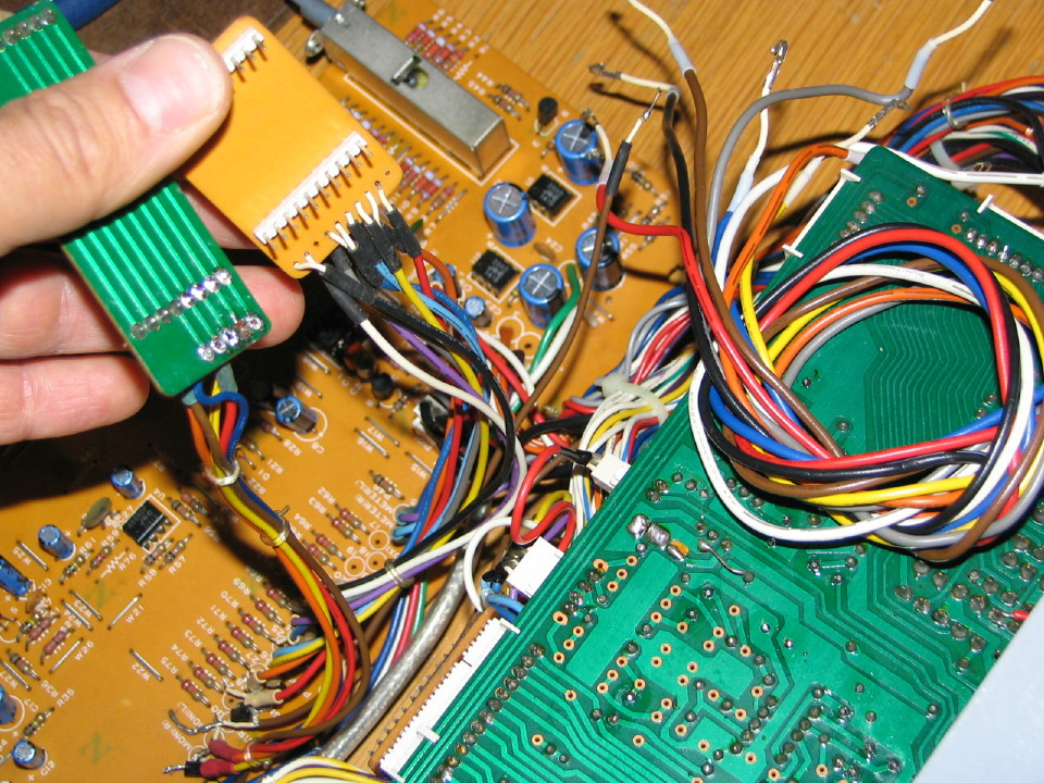
some connection I had reseated had fixed things, but I haven't mapped the connections for the master section. That would have been good to do at some point and I 'm sure I will someday, but it is going to be time consuming. So I was encouraged that it was looking more like it wasn't a component failure, but rather a flaky connection...much less like it was coming apart and more like typical old mixer stuff to fix...but discouraged not knowing where the problem was, and unable at this point to identify what all the connections do...I wondered if it could be the connection from the motherboard to the PCB...the connections look clean and appear visually to be making good contact. I have not applied DeoxIT to them though nor have I flexed contacts to make sure there is good contact. This morning I tested the theory and at this point it does indeed appear that it is just an issue with the connectors between the motherboard and the PCB.
")
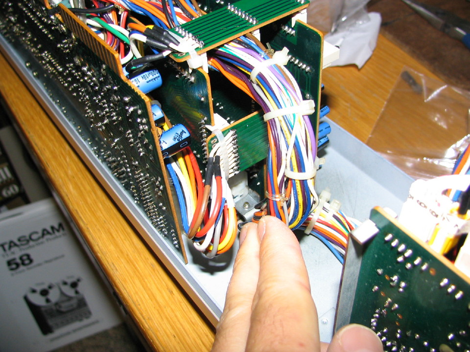
I was able to put
my tweaker on effected connection points, apply pressure and make and break signal. I was able to get everything to work, so needless to say its time to flex contacts in the socket on the motherboard and apply DeoxIT and do some reseating. This would be awesome. And it gets better...
Remember how I've been ruminating over the DIM control that hasn't been working? At least I
thought it wasn't working...
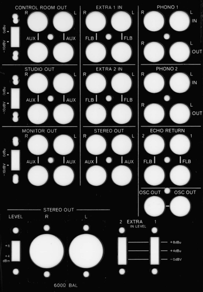
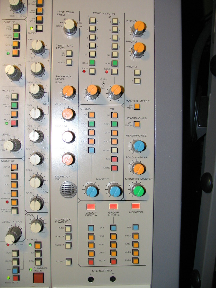
IT IS! I don't know what I did wrong before...I can't remember my testing methodology from before, but the MUTE and DIM controls are, of course, in the CONTROL ROOM switchrack...they allow the board operator to quickly MUTE the output to the monitors or diminish (DIM) the output (probably by, like, -20 or something) so you can still hear the program but hold a conversation to discuss something, and in both cases make no changes to the CONTROL ROOM MASTER level pot...so those functions should only effect the signal at the CONTROL ROOM OUT jacks. They both work...I must have had things connected to the wrong jacks or something or been monitoring in the wrong way...its easy to do (for me) since the master section has so many monitoring, sourcing and routing options...
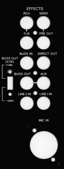
So if doctoring the motherboard connections fixes my channel issues in the master section, the last conquest is to investigate the output level switching issues in the master section. The CONTROL ROOM, STUDIO and MONITOR OUT jacks all have switchable nominal output level capability, -10dBv or +4dBu unbalanced. IIRC 1 or 2 seemed to work, and 1 or 2 did not...not a deal breaker, but you know me...I want everything to work and I'm getting reinforcement here that, even though it is a prototype mixer, everything on it seems to be functional. So I'm hoping that since I bungled the testing of the DIM function I had something connected or switched wrong when I was testing the output levels. If they don't all work I'm going to leave that one alone at this point. Its not critical. If the other stuff is working (and another big thanks to evm1024 for his help with the oscillator

), then it is time to put the dress panel and knob and switch caps back on the master module and call it "done"!
To be continued...


 :rolleyes:")

") Then again, you've cleaned that thing up so well there's probably not a chance.
Then again, you've cleaned that thing up so well there's probably not a chance.