Tascam M-___ Story...

  • Thread starter Thread starter sweetbeats
  • Start date Start date
Now we're gettin' somewhere...

In the past week, here and there, I finished cleaning up the master fader, finished the recap job on the 4 Control Module main PCB's, and then last night stuffed and soldered in the new caps on both Balance Amp PCB's including some new resistors that had old bypass electrolytics on them...figured it'd be better just to pull the whole resistor/cap array and stuff with new rather than try to get the old cap off the resistor and clean up the resistor...was hoping I could fit both cap and resistor tails through the holes in the PCB, but they wouldn't fit and the pads are so small I figured it'd be better to piggy-back the caps on the resistor tails rather than drill out the holes...found a nice way to wrap the tails of the cap on the resistor so that there is a really nice weld between the two and the cap sits right on top of the resistor.

And the coup de gras to cap (sorry for the pun) off the evening was that I actually got the Control Module completely reassembled (except for the dress panel and knob and switch caps...leaving those off until after the smoke test).

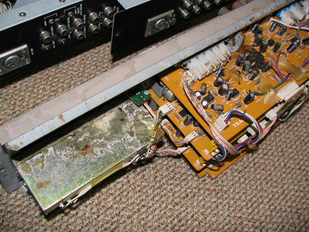
Remember this? This is a before of the master fader and the first PCB with the rodent excrement on it...the proverbial "before" picture:
Control%20Module%20Fader%20and%20PCB.JPG


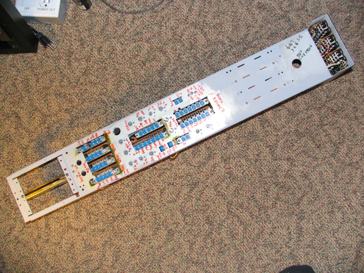
Here is the "after" pic:
Module%20Reassembled%2c%20Fader%20and%20PCB.JPG


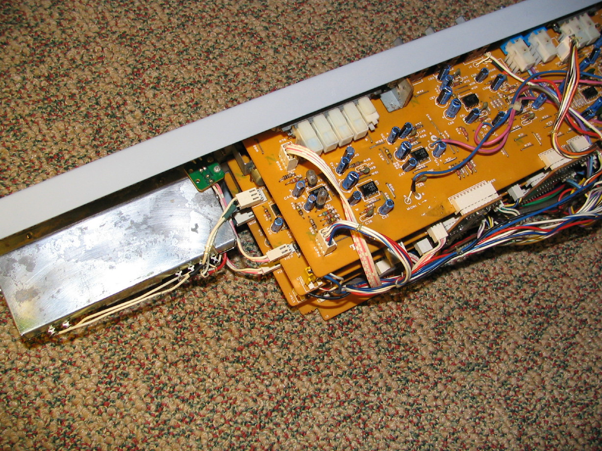
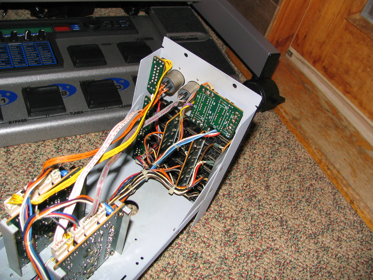
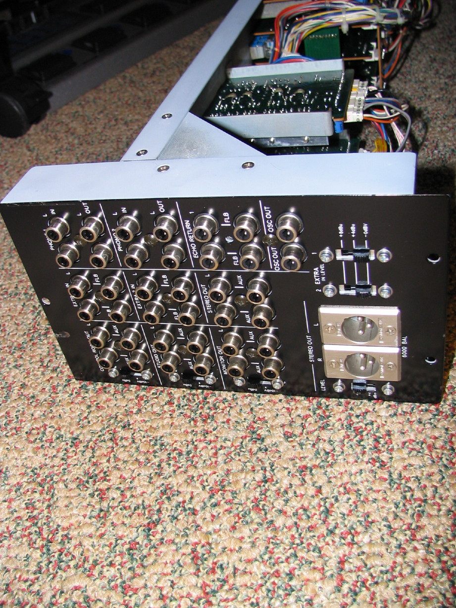
Here is a couple shots that cover the main PCB's and an internal shot of the jack panel:
Module%20Reassembled%2c%20PCB's.JPG

Module%20Reassembled,%20jacks%20internal.JPG


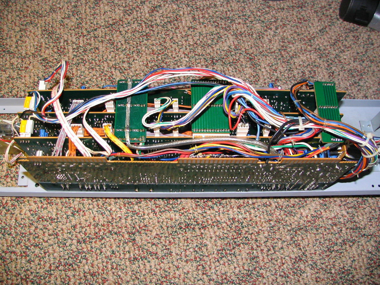
Here is one of the top...doesn't look much different than before but it will once the dress panel and knob caps go on:
Control%20Module%20Reassembled,%20top.JPG


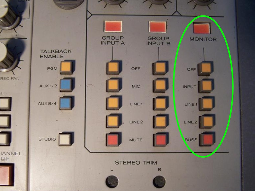
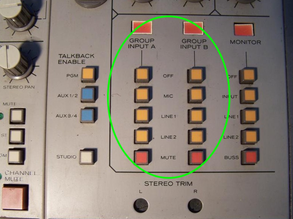
And finally here are a couple before shots of the jacks:
mixing%2520console%2520006.jpg

mixing%2520console%2520005.jpg


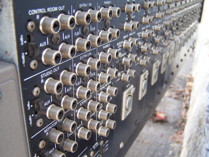
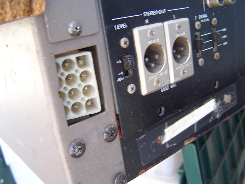
And here is the after:
Module%20Reassembled%2c%20jacks%20external.JPG


Sometime in the next couple days I'll smoke test it, :eek: and if it passes that and some preliminary audio tests I'll put the dress panel and knob/switch caps back on. ;)
 
Last edited:
Man, that thing looks new again! I swear, You and Ethan could make a couple of bucks on the side restoring stuff.:)
 
Control Module passed the smoke test. :D

Tested some of the audio functions. This thing is dizzying. Initially could only get the right channel through the STUDIO section but I got that working. Lots I haven't tested yet, but it will take some time. Layers of routing...I do know that the REMOTE section functions as I thought...two remote channels (A and B) each with the same three source options (mic, line1 and line2). Select, for instance, mic as the source for channel A, and then ENABLE REMOTE A on any channel strip and instantly that channel becomes a group fader for all the mics connected to channels 1~ 12. There's much more to it that still escapes me...

Anyway, I'm going to try to test everything before I put the dress panel on.

Oscillator: works, but not 400Hz so well. Turn it to that tone and it fades out...switch it to any other tone and it comes back...Any ideas where to start sleuthing?
 
I definitely don't know too much about oscillators. But I imagine that there has to be an actual oscillator device on the PCB somewhere. Have you checked that component for bad solder joints?

My thought is that if the volume is fading out only on the 400 Hz oscillator, but the other frequencies are working fine, then it sounds like the oscillator itself is doing its job in that it's generating the proper frequency. But something either built into the component or attached to it is causing a leak of amplitude. No idea where I would start with that, but just my thoughts.
 
Thanks, Muck...yeah, I'm thinking it may be a bad resistor or a problem with the opamp feedback network or something or even a bad opamp...still fuzzy on that but that is my hunch. I do have spare TL072's laying around so I could put those in and see...just hate to be shooting in the dark and I'd like to have a little better grip on how it works.

I think the basic premise of the circuitry is like the M-512/520 tone generator. Here is the schematic:

M-512_520%20Talkback%20PCB%20Schematic.jpg


Any suggestions anybody? My understanding is that the oscillator itself generates a sine wave and then that goes through an amplifier and then that can be directed through different resistors via the frequency select switch which changes the frequency of the tone...is that right?

I think the M-___ uses JRC386D opamps in the tone generator circuit. I'll have to look closer at the traces on the PCB. Circled the 386's in green and labeled a couple other components of possible interest. There are new caps there now.

OSC%20Snip.jpg


Big picture question is what could be the cause of the fading 400Hz tone. I could put up an audio snip of it as well. 64Hz, fine. 1kHz and up, fine. Switch to 400Hz and it fades out after 3 seconds or so. Switch it to 1kHz and the amplitude pops right back. Switch it to 400Hz it dies, switch to 64Hz and it takes several seconds for the amplitude to reach unity.
 
Last edited:
ANYBODY have any additional thoughts on the oscillator problem?

Still looking for any pointers on the flacid 400Hz tone...

On another note, did some more testing last night of the Control Module functions. Not all the way through yet but about 60% done. The only other problem that's come up is that the EXT1 and EXT2 inputs (two sets of fixed-level stereo inputs that can be routed to either the CONTROL ROOM or STUDIO outputs) are only passing the left side. hopefully easy to find that issue.

Here's the fun stuff. I finally figured out what the MONITOR switchrack does in the master section...that's the rack of switches next to the GROUP A and B switchracks. Here...I circled the whole bunch of switches:

Monitor%20Switchrack%2001.jpg


Zooming in...I circled the specific switchrack I am talking about:

Monitor%20Switchrack%2002.jpg


I've been baffled. I mentioned above that I confirmed what the GROUP A and B racks do:

  1. Select MIC, LINE1 or LINE2 in the GROUP A or B switchracks
  2. Go to any channel strip or combination of strips
  3. select A or B in the REMOTE switchrack on any channel
  4. latch the ENABLE switch and BAM! That fader is now a master fader for whatever group of inputs you selected via the GROUP A/B switchracks in the master section.

REMOTE%20Switchrack.jpg


So what of the MONITOR switchrack then? Couldn't figure that out. Also couldn't figure this button out on the channel strips:

MONITOR%20REMOTE%20Switch.jpg


Well, you guessed it. That ties to the MONITOR switchrack in the master section. So you can, on any one or combination of monitor sections on the channel strips instantly drop in all INPUTs, or LINE1 or LINE2 inputs or the "BUSS", er, buss. Not sure about that yet. The terms "PGM" and "BUSS" are used throught the control surface and I haven't quite figured that out yet; the difference. I believe that "PGM" is the stereo sum of the 8 groups, while "BUSS" is related to the BUSS IN jacks on each channel strip. Anyway, the ramifications of this are cool because it means that each channel strip has access to 2 pseudo matrix mixers (one at a time per channel), and in turn those matrix mixers (GROUP A and B) can access any of three 12 x 1 mixers...the levels are dependent on the TRIM settings for those "mixers" (the TRIM knobs for the MIC, LINE1 and LINE2), but you could instantly source, like, 12 DAW returns and literally mix them from the TRIM knobs and then using internal and external access points drop that mix in or send it out in a number of ways. And then totally separate from that is the access in the MONITOR section of each channel strip, and there you have access to four pseudo matrix mixers. If the "BUSS" means the BUSS IN jacks that is a whole separate 12 x 1 sub mix. And the monitor mixer can be sent and/or accessed in a number of different ways. And notice that the top switch in the MONITOR switchrack in the master section is labeled "INPUT", not "MIC" like the GROUP A/B switchracks. That means you can instantly drop in a pre-eq pre-fade mix of whatever is selected as the input source of each channel strip...that could be a combination of MIC, LINE1 and LINE2 inputs...like instantly pressing the PFL switch for each strip and you can get it by pushing two buttons and it goes to the dedicated and flexible MONITOR buss. I haven't tested that yet, but that is my hunch.

And BTW, I'm pushing the envelope. Put 3 strips in at once with the Control Module. :D Not expecting to overtax the PSU, but it is reassuring that everything works. And meter functions all seem good too...been testing those.
 
Last edited:
come on dude you can do it... what's common to all three tones??? and since the other two work we can eliminate those portions... right??? so what's left??? the 9 resistors (3sets of 3) and the switches... and two of the three work.... so??? :D
 
demented, I'll try to correlate. I don't quite understand...I may not be being clear.

The schemo is from the M-520. No problems with that oscillator, and yes it is 3 tones, and I understand the correlation, sort of. Factors of 10 (100Hz, 100Hz, 10000Hz). I don't quite understand the 3 sets of 3 resistors. I think I get that each set corresponds to one of the tones and I'll look at the values and see if I can recognize where those "sets" are on the M-___.

The pic of the PCB is from the M-___. That's where there is an oscillator problem. There are five tones on that one, 64Hz, 400Hz, 1000Hz, 6400Hz and 12000Hz. The problem is with the 400Hz tone. :o

[EDIT] Okay...I'm excited...I just looked at the PCB again and I see the three sets of 5 resistors...The higher the resistance the lower the tone so the second highest valued resistor goes to the 400Hz tone right? So I could pull the three resistors of that value (at least one leg) and measure and betcha I find a bad one in the bunch YAH????
 
Last edited:
Osc problem....

OK let's see if I get it right. Turn the osc on and you hear a tone, Switch to 400 Hz range and it fades out. Switch to another range and it fades back in. Sounds like a cap charge/discharge time constant at play.

2 things come to mind.

First, power is not being sourced when 400 Hz is selected. Test: turn unit off, wast for PS caps to discharge. Select 400 Hz, power unit on. Hear anything? (no power, no tone) Turning on with 400 selected starts out with a presumed electrolytic not charged.

Second, A fet switch to turn Osc output on to the bus is being biased off when 400 Hz is selected. Look for the fet switch(es).

--Ethan
 
Thanks, Ethan.

That makes sense...mostly. :o

I did the power up test and indeed the oscillator is dead if set to 400Hz when the discharged mixer is powered up (there is a brief, very brief hint of the tone, but for all intents and purposes its dead) whereas if it is set to anything else it fine.

FET's...same thing as a transistor? I will look at the M-512/520 manual to see if I can identify them there and make a correlation to the M-___. But the idea is that one or more is not switching so the tone signal goes to ground and a cap discharges temporarily supplementing the lack of current from the amp?
 
FET = Field Effect Transistor. The 2 major transistor families are FETs and bipolar. THis is where the types of opamps come from - the input transistors internal to the opamp (FET or bipolar).

So if it does not work when powered up I would suspect the selection switch. My presumption here is that the switch not only selects the frequency but also applys power to the tone generator. Being off when not needed removes the chance of a tone cross-talking into your audio path.

-Ethan
 
Hmmm...bummer. Thinking of the easiest way to confirm...should be able to just test for continuity pole to pole on the switch yes? I'm sure if the switch is bad I'll have no trouble finding one of those... :rolleyes::rolleyes::rolleyes:

Last night during testing it seemed as though the length of time it took for the tone to die out was longer. I've shot the switch with DeoxIT...maybe I'll try some more of that too and exercise it.

So it wouldn't be an opamp because the issue would likely occur with other tones right (making lots of assumptions there I know...but if it was designed logically right)?

Worst-case-scenario I'll take the switch apart and see what I can do if that's indeed where the problem is...
 
Not wanting to bury the topic about the tone generator problem, but I thought y'all would want to see this:

11%20Strips%20In.JPG


That's 11 of the 12 strips installed and powered. Of course none of them are cleaned up and I've only done partial function testing on 3 of them, but I figured full testing on the master section would be a whole lot easier with as many strips installed as are put together since they are inline and all the PGM group I/O and AUX buss I/O resides on the channel strips...kinda hard to see if the talkback mic is routing to the full slate without the BUSS OUT jacks. :D

In the meantime, since I'm on a roll cleaning up M-520 channel strips I decided to throw a set of M-___ channel PCB's into the mix. Cleaned up a set of the PCB's and jacks last night...the ones from channel #1 that have been apart for my M-___ anatomy studies and wiring diagram that I drew up. So I cleaned them, cleaned the pots and switches and all that and since I have all the caps needed to recap the entire board I'm going to do this one channel strip and see how it compares sound-wise to the rest of the strips. I'm also going to socket a bunch of the opamps. Pulled the caps off of 3 of the PCB's last night and removed 10 opamps. I don't think I'm going to socket more than that. IIRC there are a total of 19 opamps on each channel strip. I don't see any reason to upgrade certain opamps...more upgrades means more $$$ and greater risk of overtaxing the PSU...might already be headed there with what I'm thinking of doing. Anyway, I'm socketing all 6 of the EQ section opamps, the MIC preamp, the direct out driver, and I want to figure out which IC handles the first stage on the jacks I'd use as tape returns (LINE2), as well as the first stage of the STEREO summing buss, and I need to look at the PGM groups. I will likely be using each channel 1 ~ 8 hooked direct to tape inputs so I'm mostly going to utilize the direct out jacks and tape returns, but the flexibility of the PGM groups is so great too and 4556's and 2041's are used there and I'm thinking that could be cleaned up with modern opamps. We'll see. I think that's all on the channel strip. Later I'll look at the master section and see if some upgrades in the stereo buss might help as well as the CONTROL ROOM buss. Outside of those areas I don't see why it would be necessary to upgrade opamps on monitoring type busses like the MONITOR buss and AUX busses on the channel strips or the STUDIO and MONITOR outs in the master section...or the GROUP A/B busses. I can see where the AUX and MONITOR busses might be considered, but AUX busses will only be used as cue feeds or effects sends. Cue feeds don't go to tape, and effect sends won't usually be used 100% wet. I'm trying to focus on those paths that will be direct print and mix paths from tracking to mixdown and those that are used for critical listening by the engineer and that is going to be the STEREO buss monitored via the CONTROL ROOM out.

Let me know what I'm missing in my ideology. Several of you have had some really great educational counter-point in the past as to the traditional use of different paths on a recording console and it has helped me view things in a different way and this may be another of those opportunities. :)

OH! Forgot to mention I busted another pot shaft. :mad: 
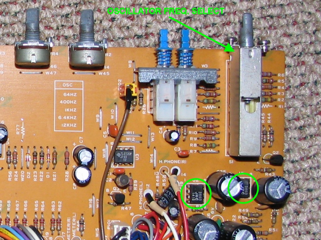
It was the low band frequency sweep pot on the EQ board, and no I wasn't being obsessive. Didn't see it earlier but it had gotten bent so bad in the past that it wouldn't even turn. Now in my world that has to be fixed. Figured it wouldn't sustain straightening but I did my best. Secured the card to the channel frame via nutting some of the pots (of course including the bent one) and found a great wrench in the toolbox...just about fits over the pot shafts right. It is one I got to open/close the brake bleed valves on an Austin Mini I used to have. Anyway, snapped that sucker right away, but I happen to have a pot with the same body and shaft that was on a broken M-520 strip so I'll replace the shaft like I did on a couple others. This should be easier since it is not a stacked pot. :p
 
Last edited:
yes... i'ld be looking at those resistors and the switches themselves... i'm assuming that the circuit here is essentialy the same as the 520 manual shows... and i dont see any fets being used there... but if there were i wouldnt expect them to be the problem since they would be working at other times... my money's on a solder joint on the switch or a contact itself... remember alotta repairs come down to physical issues...
 
Right...right. Thanks, demented. I'll see what I find. ;) I looked at the foil side of each PCB really close and identified a number of little repairs that were needed, but there could be something there that I couldn't see. Might just touch the iron to the joints for the 400Hz tone path. That's be a quick and easy thing to do...
 
This is going well...

I tested every jack and function of the Control Module last night (except the PHONO1 and PHONO2 inputs...no turntable), and 'lo and behold everything works and works great aside from the 400Hz tone (and I'm not totally sure yet if the output level switches work on the CONTROL ROOM and STUDIO outputs...it'll be easier to tell using the oscillator and metering it than using my voice routed to headphones). That is just short of a miracle AFAIK considering that there is some definite funkiness in its construction, its age, and the fact that it was a rodent bathroom and has been knocked around and mistreated.

It was a whole lot easier to do the testing with the 11 channel strips installed, and it also gave me a chance to get to know the operation of the mixer...I've done so much studying and thinking that it felt pretty natural to get around and do what I needed to do on the control surface. At this point I know some things about the 11 strips also (and yes there is a lot below...I'm seeing posts like this as a place to keep notes so I can recall this stuff later...I'm documenting and you get to read it or not :)):

  • Each is passing audio from the strip to the STEREO buss, and I have to say that it is nice having a true stereo buss unlike the M-500 series. There isn't a routing switch per se (like you would see on a modern dual-purpose 8-buss board for instance...usually there are routing switches for 1-2, 3-4, 5-6, 7-8 and L-R), but there sort of is since there is a mute switch just for the output to the stereo buss, so it just sort of works the inverse of a routing switch.
  • The MONItor buss is working on each strip as is...
  • The BUSS MASTER knob which is PGM groups 1 ~ 8 on strips 1 ~ 8 and AUXes 1 ~ 3 on strips 9 ~ 11 (remember I don't have the 12th strip in which would handle the AUX 4 sum) EXCEPT for the strip that is in bay #1...that was originally installed in bay #12, and it is also one that I happened to notice some permanent marker markings on the BUSS PCB...circles, lines, arrows, and there is a resistor that is in a different place and a trace interrupted with a scratch. The BUSS OUT path works, it is just bypassing the BUSS MASTER knob. So I'll look at that when I get to cleaning that strip up. Either they wanted the BUSS OUT to be fixed at unity gain or there is a problem with the pot or something. I'll put it back like the others and see what happens since I want the BUSS OUT to be adjustable.
  • I am positively shocked at the lack of noise in the pots and switches...seriously...after all I've been through with my M-520 I figured for sure the pots and switches on this thing were going to be crunchy and crackly and the routing switches were going to be intermittent and all that...figured everything from this era must be that way and considering this thing looks like it has not been cared for in the least I just couldn't believe it last night. The functions mentioned above that I used on each channel strip are, almost without exception, crunch/crackle/static-free. There were a couple pots here and there that would be a little static-ey, but literally 5 sweeps of the pot knob and the extraneous noise would be gone. :eek: Maybe it makes a difference that it has lived in California and the M-520 lived (and was stored for years) in Washington?
  • I'm a dummy...I was wrong about the whole GROUP A/B ~ REMOTE function. I said a couple times earlier that it changed a channel strip into, like, a group master for whatever is selected via the GROUP A/B select switchrack...nope...but what it does do actually makes more sense and is pretty cool. It allows for a per-channel drop-in of whatever is selected as the REMOTE GROUP source in the master section. Okay...in English: Let's say you've got mics connected to the MIC jacks on channels 1 ~ 8, and two different 8 track decks connected to the LINE1 and LINE2 jacks on channels 1 ~ 8...that make sense? Deck A to LINE1 in 1 ~ 8, and deck B to LINE2 in 1 ~ 8...now if I quickly want to be able drop playback from those decks to the STEREO buss I depress the LINE1 switch in the GROUP A switchrack in the master section, and then depress the REMOTE ENABLE and 'A' switch on strips 1 ~ 8. I'm now sourcing the LINE1 in 1 ~ 8 jacks. Press the LINE2 button in the GROUP A switchrack in the master section and I'm now sourcing the LINE2 in 1 ~ 8. If I want to mix the REMOTE sourcing of LINE1 and LINE2 I can set GROUP A to source LINE1 and GROUP B to source LINE2 and then toggle back and forth on the channel strip. And each GROUP A/B has a master mute switch. Not sure if that allows the channel source to pass. I think not. I think if the ENABLE switch is latched on the strip then the GROUP source is passed to the STEREO buss. I assume the channel source is still available to the AUX busses, PGM groups and MONITOR buss as I think GROUP A/B sources the selected input right after their respective TRIM knobs and then routes direct to the STEREO buss. The MONITOR switchrack in the master section is then the same way. Select the MONITOR group source via the switchrack in the master section, depress the REMOTE button in the channel strip MONITOR section and you are then sourcing whatever input on that channel that has been defined by the MONITOR switchrack in the master section. Still trying to get my head around how this would be useful, but it would give very quick access by the press of one button to be able to monitor back and forth between 3 x 12 sets of inputs as long as the REMOTE switch is latched on each strip's MONITOR section (i.e. INPUT, LINE1 or LINE2), and 12 outputs (i.e. BUSS). I was trying to figure out the easiest way to, for instance, monitor the AUX masters. Well, there ya go. Select BUSS in the MONITOR group switchrack in the master section, latch the REMOTE button in the MONITOR section of channels 9 ~ 12 (because the BUSS MASTER knobs on those strips are passing the AUX 1 ~ 4 sums respectively), and now you can monitor the AUXes. And since there are MUTE and SOLO controls just for the MONItor section, you have total control over which channels of the MONITOR mixer you want to listen to...come to think of it, skip the REMOTE path...there is a BUSS source button on each channel's MONITOR section switchrack. You could source the BUSS for channels 9 ~ 12, MUTE them all and then hit the SOLO button to monitor one AUX master at a time...and it is solo-in-place as well...sheesh...that's the thing with this board. You have, like many Tascam mixers of the day, 3 inputs per channel...actually there are 4 if you include the BUSS IN jacks which I think I now understand are fixed level sub inputs that can be sourced when selecting the BUSS as the source in each channel's MONITOR section, or via the MONITOR group switchrack in the master section and then via the REMOTE button in the MONITOR section of each channel...anyway...so 4 inputs per channel...that's 48 (54 total if you count the additional inputs in the master section, 4 of them stereo...), and I believe it is possible to get them all to the STEREO buss simultaneously in a variety of ways...I'll have to figure that one out just for the exercise...It will help me become more familiar with the control surface.

I also finished pulling the caps off the rest of the channel strip PCB's on that one that I'm working on. Haven't finished deciding which IC's I want to socket.

All things considered, this board is proving to be a solid performer.
 
Oscillator and Master Fader Updates...

This post restores some info that got lost in the database crash and combines it with updates.

I'm basically grappling with two issues right now:

  • The dying 400Hz tone on the oscillator, and...
  • An issue with the STEREO buss which I thought was a dead left channel but actually turns out to be a right channel that won't quit which in turn is actually a simple faulty wiring issue which has now morphed into wierd fader behavior. More on that below.

I'll start with the oscillator issue.

The dying 400Hz tone:

I pulled the master section and removed the TEST OSC PCB which has the tone generator on it. Turns out that the oscillator is driven by a TL072 opamp. Thought it was the 386 chips...nope. Those are for the headphones! :eek: Might be some beneficial upgrades that can be done there???

Anyway, I tried testing the poles of the switch, but there are, like, 28 of them and I'm not sure that I can really tell anything without removing the switch...couldn't make heads or tails out of what I was seeing on my DMM, so I resorted to re-welding all the switch solder joints as well as the resistor solder joints...added a little solder to many of them as well. Also noticed that there is still gunk around the above mentioned solder joints so I used a very small screwdriver tip, some 70% iso alcohol and a toothbrush to clean that up...wet toothbrush with iso alcohol, scrub-scrub-scrub and immediately dab dry with a terrycloth towel. Repeat as needed and use some canned air when all done to get it really dry.

So after all that, as well as reapplying DeoxIT to the switch (found some better spots through which to inject the DeoxIT) the 400Hz tone still doesn't work, though I noticed immediately that it took longer for it to die out...like 5 ~ 10 seconds. And then when I tried it a couple days ago it now takes about 30 seconds to completely die out.

Anyway, thinking of pulling the switch and one leg of each resistor and testing. Any other ideas anybody??


Master fader issue:

Okay...So, a couple weeks ago I thought there was a dead channel problem, but I wasn't really paying attention to the conditions of the control surface, and I realized a couple days ago that the master fader was all the way down an I could still hear audio through the STEREO buss...this was true while monitoring through the headphones or any of the outut jacks that pass the STEREO buss...so I wasn't lacking a channel, the right channel was bypassing the fader and passing at unity gain. I acted on a hunch and wiggled the fader wires with the system powered and sure enough, intermittent connectivity. Pull the fader out. The contacts in the plug for the right channel looked corroded so I decided to pull them out and have a look. hey came apart when I removed them! :eek: That's rodent pee for ya.
Broken%20Fader%20Plug.JPG


So I wanted to redo the wiring. I've got spare faders and I figured i'd be easiest to pull wiring from those, but its like the M-___ faders were installed backwards from the likes of the M-500 and M-300 mixers. This only mattered because of the way the shield wire was run. So it took a little bit of thinking but I figured out how to reassign the contacts in the plug so I could put the fader in in reverse and have it still work while being able to make good us of already complete assemblies.

Look back in post #281. There's a decent "before" shot of the fader. Here it is with new wiring:
Fader%20Rewired-2.JPG


SO...I put it back in but there was something I noticed when I was testing the fader while it was stripped that I hoped was just some freak occurrence or something, but now that I was testing it with an audio signal I could tell something was very wrong.

Its not a log or linear taper fader...Its, like, a bunch of hills. I saw this on the DMM prior to putting the new wires on.

Here's a video that might explain it better:

YouTube

Its about 5Mb, but it basically shows me passing a 1kHz tone through the STEREO buss and you can hear (and see with the VU's) the peaks and valleys.

Ideas????
 
Last edited:
HUH -- that's the oddest thing I've ever heard! An an annoying little sonofabitch isn't it?

I'm starring at your photo of the guts of your fader. I see two traces that go the entire length of the fader, and there's about 7 small variable-length square-shaped traces on either side of it at certain points along the length of the fader. Do the drops in volume correspond to the positions of those small traces?

Heck, what are those small traces, resistors? I don't know enough about the inner workings of a fader to tell you HOW it fades, but if I had to guess, I'd say it may have something to do with when the fader hits those small points in the path.
 
Muck,

Yeah, I was going to look at those spots. I don't think that's the issue, but I think you are right to bring that up.

Basically, if I understand correctly, the way a fader works is that you have an input, and output, and a ground. The 'resistive element' (any of the black strips you see in the picture) increases in resistance as you get further from the input point. The slider that the fader knob is attached to has a 'wiper' on it. It contacts the element. In the most basic sense the signal comes into one end of the strip, and goes out through the wiper...the further the wiper gets from the input point the higher the resistance. Think about it like standing in front of a light on a foggy night. The light is the input point, the fog is the element, and you are the wiper. Start walking backwards and the further you get from the light in the fog the more dim it becomes because of the increasing amount of resistance to your visual contact with the light due to the increase in the amount of fog.

Those particular faders in the M-___ I've seen in other older Teac mixers...they boards in them appear to be setup for a number of applications...mono, stereo, and then there's all the little blocks. I believe those are for applications where certain machine functions are tied to fader actions/positions (i.e. auto start when the fader is raised). I don't believe that the wipers in my master fader are off track, but that would cause a problem if they were because it would effect the the resistance at certain points in the fader travel...I'll have to take a closer look.

Might be needing a new fader. The board looks really good but...:???: Anybody have one of these faders laying around?
 
Back
Top