Tascam M-___ Story...

  • Thread starter Thread starter sweetbeats
  • Start date Start date
Duh...

I figgered out the whole mic input pin assignment confusion...schemati 4-18 in the M-500 manual is a nice big wiring diagram that shows how all the guts interconnect...it includes the actual mic jack...the schemo for the channel card doesn't include the mic jack, just the connection from the input PCB (to which the mic jack connects). Why does this matter? Because XLR pin 1 goes to input PCB terminal 2, XLR pin 2 goes to PCB terminal 1, and then pin 3 to terminal 3. So what was confusing on schematic 4-15 is no confusion at all once you realize that what is shown as 'pin' 2 on the channel card PCB does not mean XLR pin 2...it is actually XLR pin 1, which makes sense.

Phew.

That's what post 238 is all about - I better practice my english :o

--Ethan
 
0V(D) is tied...

So I'm getting pretty comfy pulling the main PCB out of the PS-520... :rolleyes::)

Pulled it out and scoped out my plan, part of which was to review the schematics to have one last look to see if (within my knowledge ability) there might be a problem with what I was about to do. Nope...basically the plan would result in a PS-520 main PCB that matches the schematic (remember that in the schematic, 0V(D) is already tied to the ground buss in the PSU, but the production version of the PCB has that tie occur in the mixer...)

The trace for 0V(D) is really close to the ground buss trace, so I decided to build a bridge using scrap capacitor tails. In this picture you can see how close they are...to the left of the tool tip is the 0V(D) trace, and to the right is the ground buss trace.
0V(D)%20mod%20%231.JPG


Scraped away the protective coating and cleaned with iso alcohol...
0V(D)%20mod%20%232.JPG


Here you can see my scrap cap tails tacked in to the 0V(D) trace...
0V(D)%20mod%20%233.JPG


Snip the tails and burn 'em in at each end. Tested good using the DMM.
0V(D)%20mod%20%234.JPG


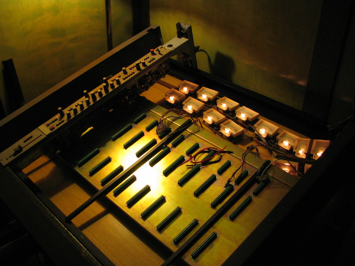
Looky! An M-___ with meters lit up and a channel strip!!! :rolleyes: (Main SOLO LED doesn't work...:mad:)
Meters%20Lit%20AND%20a%20Channel%20Strip.JPG


Point is, nothing blew up. It worked. Peak LED's light momentarily on power-up, meters give a little jump, but nothing like they did before. I even plugged a mic into the strip and the appropriate meter responded, and then I assigned the input to the corresponding PGM group and switched the meter source to BUSS and sure enough it worked just like it should. ;)

I must say, though, that with the meters powered and the one channel strip installed the test light is glowing brighter. I'm not comfortable with this. Should I be? Is it just the demonstration of the current draw at idle of the circuitry; those nearly 3 dozen opamps?? Here's what it looks like:
Test%20Light%20Concern.JPG


I suppose I could hook the test light up ahead of the M-520 and see if it does the same thing...
 
Last edited:
The main Solo LED...

I'm not sure if the diode is good or not yet, but I found that the problem seems to be that the wire that goes up to the LED from the motherboard is connected to a terminal that is carrying nothing...the terminal that carries the 15V when any SOLO function is engaged is in a completely different spot...I'll have to look at the underside and see if there is a trace that connects the two and if so find out why the current is not getting there...
 
Meter bridge housing is ready to reinstall

The touch-up paint from the auto body shop is fully cured so I cleaned it up and polished it...soon I will put the rest of the meter bridge framing on the main frame and mount the housing, and then finally the meters.

Shiny%20Meter%20Bridge%20Housing.JPG
 
A confidence shaking evening...

Not with the M-___...its fine...its my M-520. Probably should post this up over in my M-520 Story thread but it is related to this thread so I'm mentioning it here...

I took the dementedchord Idiot Light out to where the M-520 is perched to see if the bulb glows slightly when the mixer is on and at idle. Boy did it glow, like full on. Fault. Bummer. I'd been doing some stuff with the meter bridge on the M-520 so I disconnected it from the motherboard...still a fault. Removed the channel module that has the strips I've been modding...still a fault. Pulled power supply cable from PS-520, fault gone, so it is definitely something in the mixer. Before I pulled the harness to the meter bridge I noticed that the peak LED's stay lit, so maybe something with the 15V rails. :mad: Well, I'll have to retreat and come up with a plan for how to ferret the issue out. We've had some rough weather in my neck of the woods lately, but the M-520 has been in a temperature-controlled space totaly disconnected from power, so this is a sort of spontaneous occurrence. :(

Back to the M-___...the SOLO LED thing...I tipped the frame back to get a look at the motherboards to see if I could figure out what's happening with the master SOLO LED not lighting. Had to refer to master Control Module PCB's to try and get a handle on it but couldn't do it...I quickly got lost in the maze of traces...I have a strong hunch that the Control Module has to be installed in order for the master SOLO LED to function. So I'll just wait on that one.

The second confidence-shaker came from looking at the Control Module PCB's again...first time in awhile. Lots of hodge-podge mods and work-arounds evident on those PCB's. The channel PCB's are clearly the more refined elements of the mixer. Questions start coming...what if it was left in an unfinished state and the Control Module doesn't function or functions poorly? That kind of thing. So I decided to take a pause and tackle something that I'm more comfortable with...something mechanical rather than electrical. I got the meter bridge on.

Here is the meter bridge frame installed ready to receive the meter bridge housing:
Meter%20Bridge%20Frame%20Installed.JPG


And here is the bridge with the housing and the VU's lit up...The VU's are not totally installed...Word to the wise, since I'm sure there are lots of people that can benefit from advice on this mixer since there are so many of them...:rolleyes:...anyway, when removing the bars that hold the meters in, its a good idea to number them as you pull them out. I didn't do this and the hold-down screw positions aren't consistent. Would be helpful for putting them back where they fit if I'd paid attention and documented as I pulled them. Anyway, here it is. ;)
Meter%20Bridge%20Installed.JPG


Ahhhh. Time to stop while I'm blissfully and ignorantly "ahead".
 
Last edited:
RE Test light

Don't read too much into the test light being on.On does not equal fault.

The light is a resistor, one that glows (and changes value but lets not go there).

Take a 60 watt light, 1/2 amp at 120 volts = 60 watts. Putting the bulb in series with you mixer limits the current that can go through the mixer to a max of 60 watts. If the mixer PS has a dead short - only 60 watts will flow and try to melt it down, not a megawatts till the breakers trip. THis keeps the slag at a minimum.

With no load and only a few watts dissapated in an idling mixer you would expect the lamp to glow slightly. As you add modules it should glow more brightly. When you try to fully load it the bulb should glow quite brightly.

Lastly when you get it fully powered and attempt to dissapate more than 60 watts you will not be able to. The lamp is a resistor that limits the current. As you draw more power the voltage must go down.

In other words, leaving the bulb in the circuit is the same as operating the mixer in a brown out. If the bulb is 60 watts and the mixer needs 60 watts then the mixer and the bulb both get half the voltage....

Ohm's law always works.

Running your mixer on 60 volts would cause all kinds of supply voltages to come out strange. things would not work right.

Regards, Ethan
 
Ahh...

Thanks for your patience...you've been telling me to take bulb out of the supply chain...voltages would be wacky because of transistors and such right? Things conflicting because their getting mixed signals?

I will power the M-520 without the bulb...scary, but I understand what you are saying, and I get it now completely why the bulb glows under load. Thanks! ;)
 
False alarm

Okay...

Ethan, thank you so much for putting that last bit of advice up so promptly (regarding the M-520 and the test light). My emergency was a false alarm. Powered up the M-520 this afternoon sans test light and everything is in order. My M-520 is fine. Phew! :D
 
Good

No more smoking equipment ;) you have too many projects as it is.

Good to hear that all is OK with the 520.

--Ethan
 
  • Got all the meters installed nicely now (as opposed to sort of temporary fashion before...) Had to actually resolder one of the VU meters as the pair wouldn't fit in their respective cutouts in the meter bridge housing. :mad:
  • Removed the caps on the Test OSC PCB...that's the one with the terminals on it to connect the master Control Module to the motherboards. I have replacements for all of them on hand so I'll clean up the PCB including pots and switches and recap it in the next day or so.
  • Tested #'s 9 & 10 meters (the pair with the meter that needed resoldering/repositioning) which involved installing a channel strip into slots 9 and 10. Meters work just great and I fully tested the meter source select funtions on those strips. Very cool being able to switch the meter source from input (post fader) to buss/aux, to the monitor buss. So basically each meter is a post fader input source meter (follows whatever is selected as the input source by the input source select switch), a PGM buss/AUX buss AFL meter, or MONItor buss AFL meter.
 
So I finished mapping all the channel PCB interconnections...if I include the PCB for the BUSS OUT LEVEL switch as well as the jack PCB, each channel strip has 8 PCB's. I wanted to do a wiring diagram for them so that when I start trying to create schmatics, or even for basic troubleshooting, I will be able to quickly reference the source of a certain wire or plug. It has been a bit of a chore because the main bundle is relatively thick and I didn't want to remove any of the zip ties. I'll scan it in and post it up at some point (the diagram) just for fun. Its really messy...at some point I'd like to clean it up.

I had a very small revelation when I was trying to figure out the input fader connections; which wire was IN and which was OUT...I always thought of a fader as a gate that closed as you lowered the fader thus closing off the signal. It doesn't work that way...Am I right? This is a great example of my actual level of understanding...:D:o...its a variable resistor, and the resistance increases as you raise it...is that right? and as the resistance increases, the output voltage increases at a given point when compared to the input voltage at that same point. Did I get that right?
 
Awesome man, keep it up! You should start a business refurbing these things.... (as I pack an Otari 4-track up and ship it to you for overhaul)


AK
 
Thanks, AK...yer awesome! :)

Not that you were totally serious or anything, but I do love doing this kind of work...it would be a really fun occupation. It's kind of sad that contemporary (defined in this case as anything since the industrial revolution) commerce pushes the service industry to cut corners though...used to be there was a price to pay to have something serviced and you could be sure it would be done right for that price. It took more time and skill to do things right, and thngs were built to last and be serviced. You can't operate and make a living anymore in such a niche market IMO. I'm drawn to old-world commerce and services that had so much skill and artistic demand...the kind of trades that had apprentice programs. Not that we don't have those still, but it seems there is always such a push to do more/have more/produce more with less, and quality and depth end up suffering. Fast-food culture. I'm pleased to interact with others that enjoy and or pursue depth and quality in their work whether it be performing and recording or maintaining. Good stuff!

Tell me again what's up with the Otari? I recall that time is your biggest opponent, but is it just needing a general going-through?
 
the way most faders work is the primary contact is from the drive circuit to grnd... so the driver sees a relitively stable load... then the wiper taps in between that so you can vary the amount that gets through to the next stage...
 
Huh!

Okay, so I'm measuring with an ohmmeter between ground and one terminal and there is no change in the resistance as I actuate the fader...the other terminal to ground varies as I actuate the the fader. So am I right that the first terminal is the input, and the second is the output?
 
Voltage divider

The slider is just a pot.... It can be set up as a variable resistance which is used to control gain in an opamp feedback loop. Or set up as a voltage divider where the input (typically) is across the common and hot leads and the wiper moves from near the common terminal (lowers signal on the wiper) to the hot (highest signal on the wiper). This can be reversed.

The output driving the pot sees the Common to Hot resistance. And this load is a constant to the driver. the wiper divides the total resistance and thus divides the voltage in proportion to the resistance from the wiper to hot and wiper to cold.

Te change of resistance can be linear as the wiper is moved, log or reverse log. Reverse log is common for audio work.

For a given resistance (hot to cold) the input voltage causes a specific current to flow (I=E/R). Taking that current and using the wiper to cold resistance we find the voltage on the wiper by: E= I * R(wiper to cold).

Clearly as the wiper is closer to cold te voltage will be lower and closer to hot, higher.

---------

IN an opamps feedback the pot is used as a variable resistance.Gain of te opamp os the ratio of 2 resistors (there are inverting and non inverting configurations). Change the resistance of the pot and you change the gain.

Looking for more snow tonight! - Ethan
 
Cool...thanks Ethan!

We actually had a downpour of snow here today, right as I was ready to venture out to clean the rabbit hutch. :mad: Didn't stick though, and true-to-form it was soon sunny. Cold (relatively-speaking) tonight though.

Hey, I had one of those "why didn't I think of that before" moments just now:

You know how I've been surmising that this mixer has probably had very little use since leaving the Tascam factory, and that maybe it was indeed stolen sans power supply? Well, DUH!! Look at earlier pictures of the scribble strips on the channel strips...you can see words on them like "bass" and "gtr"...its been gigged...duhduhduh. The mystery is driving me nuts...there's a power supply out there SOMEWHERE, not that I need it, but the history and story of this thing is out there...somewhere! I'm making another attempt to reach the guy that gave it to shoulderpain at the yard sale...He responded to initial contact from me and sounded enthused and indicated he'd get back to, but never did and also didn't respond to a follow-up contact from me.
 
Holy :eek: What a thread! That is just awsome SB! Looking forward for more! :)
 
Back
Top