How to repair bent/broken pot shafts
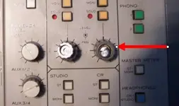
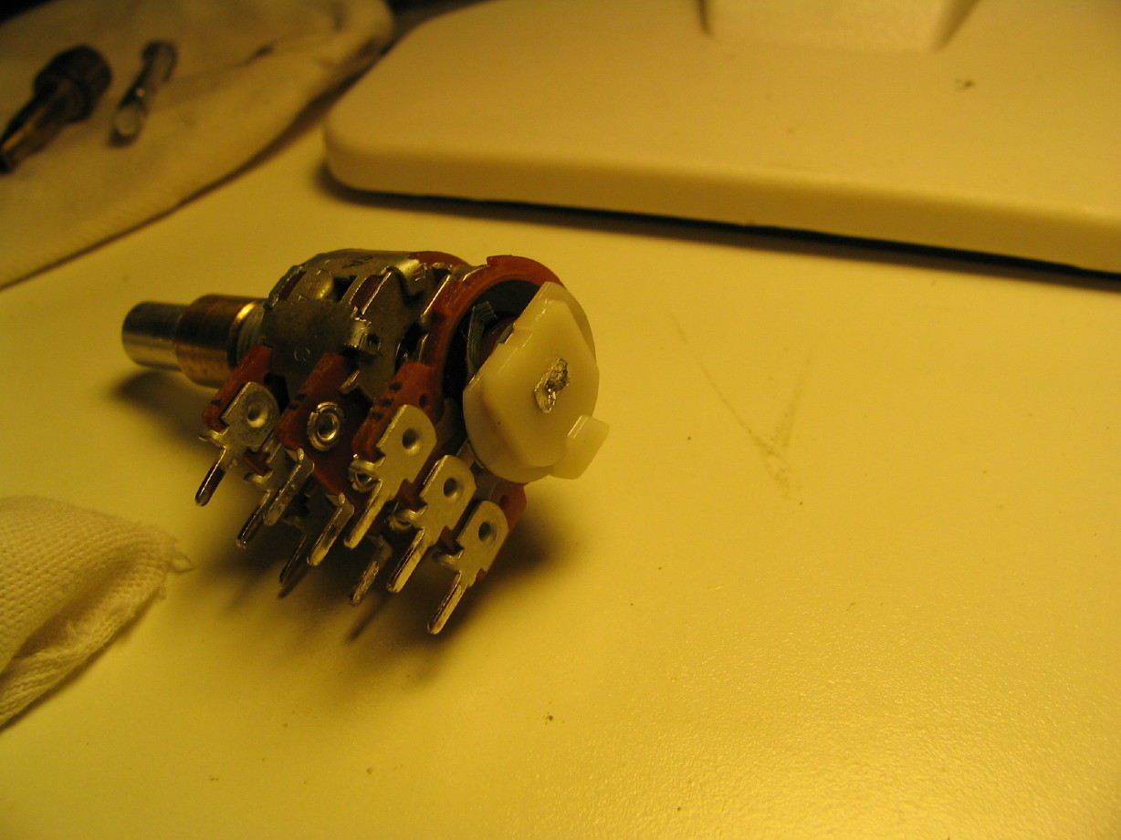
Okay...so here's the deal...The EFFECT2 return level/pan pot was damaged when I got the mixer right? I tried to straighten the bent shaft of the upper knob. It was bent so bad it didn't have full sweep range. Well if you recall it broke when I tried to straighten it.


No spares of that pot...the resistance values are unique of any Teac/Tascam mixers for which I have specs. I
do have extra stacked pots though from M-520 spares, so I started thinking "Could I actually frankenstein a pot together? Take the resistive elements and housings from the damaged M-___ pot and retrofit good shafts from another pot? YES I CAN!
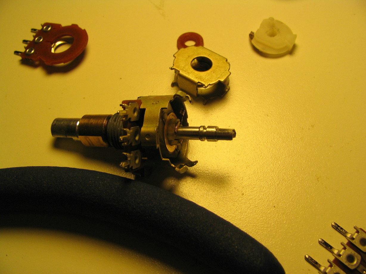
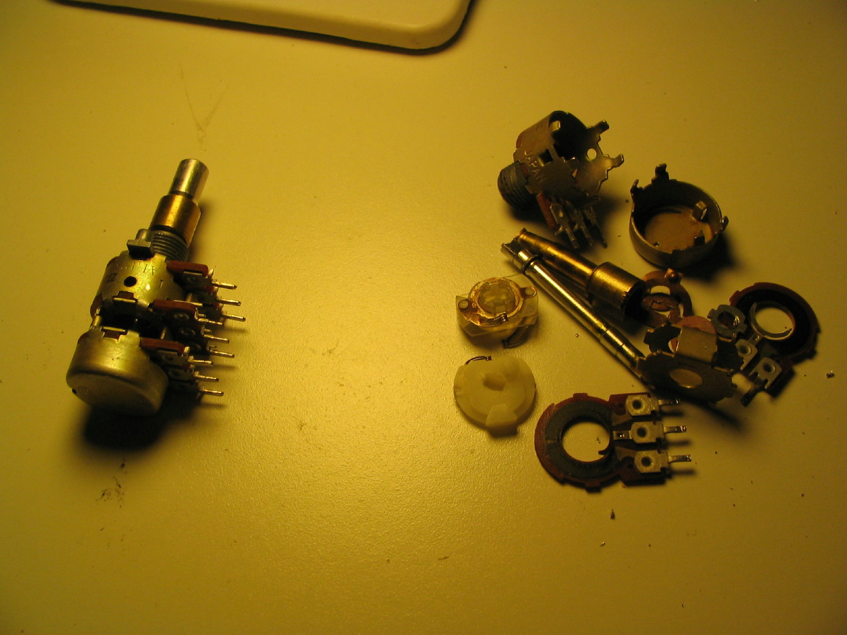
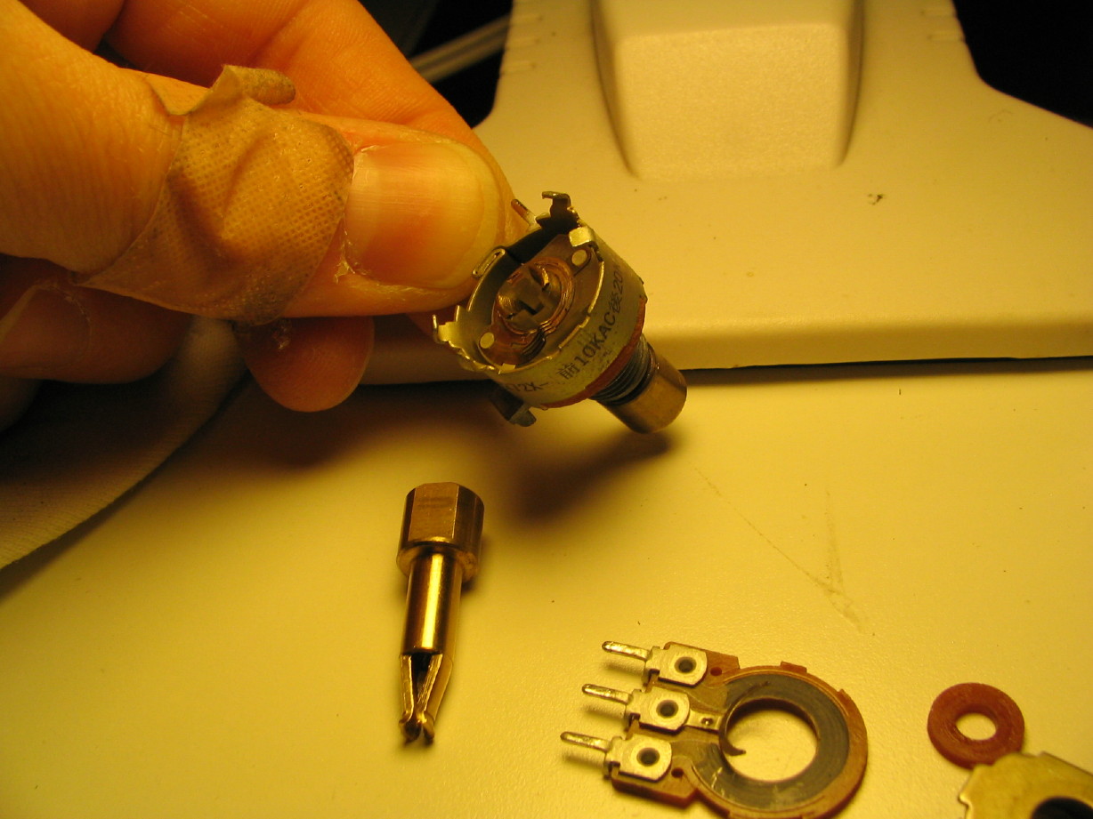
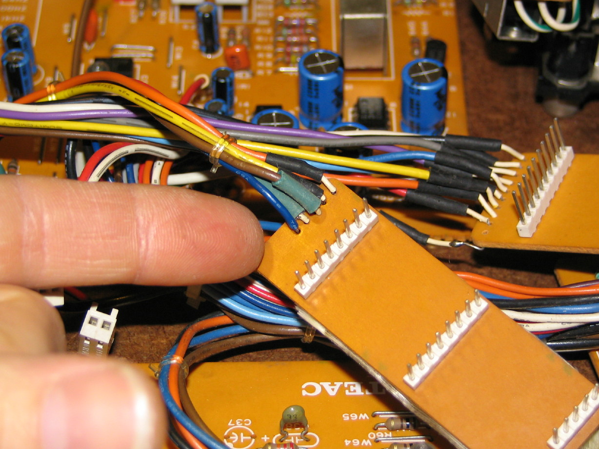
Here is the subject on the left, and my previously dismantled stacked pot on the right...You can see the little tabs of the housings bent back...you pry the bottom ones back and the bottom housing comes off. Then you have to carefully drill out the bottom of the long pot shaft (which...and don't get confused here...is the
upper knob of the stack, but actuates the bottom pot. Are you with me?) The bottom of the long pot shaft has been punched like a rivet into the wiper. Once you drill it out (and only drill out what you
need to drill out to get the wiper off...leave as much of the shaft as possible so there is something to mushroom back into the wiper when installing in the pot being repaired) you can slip the wiper off the shaft end:
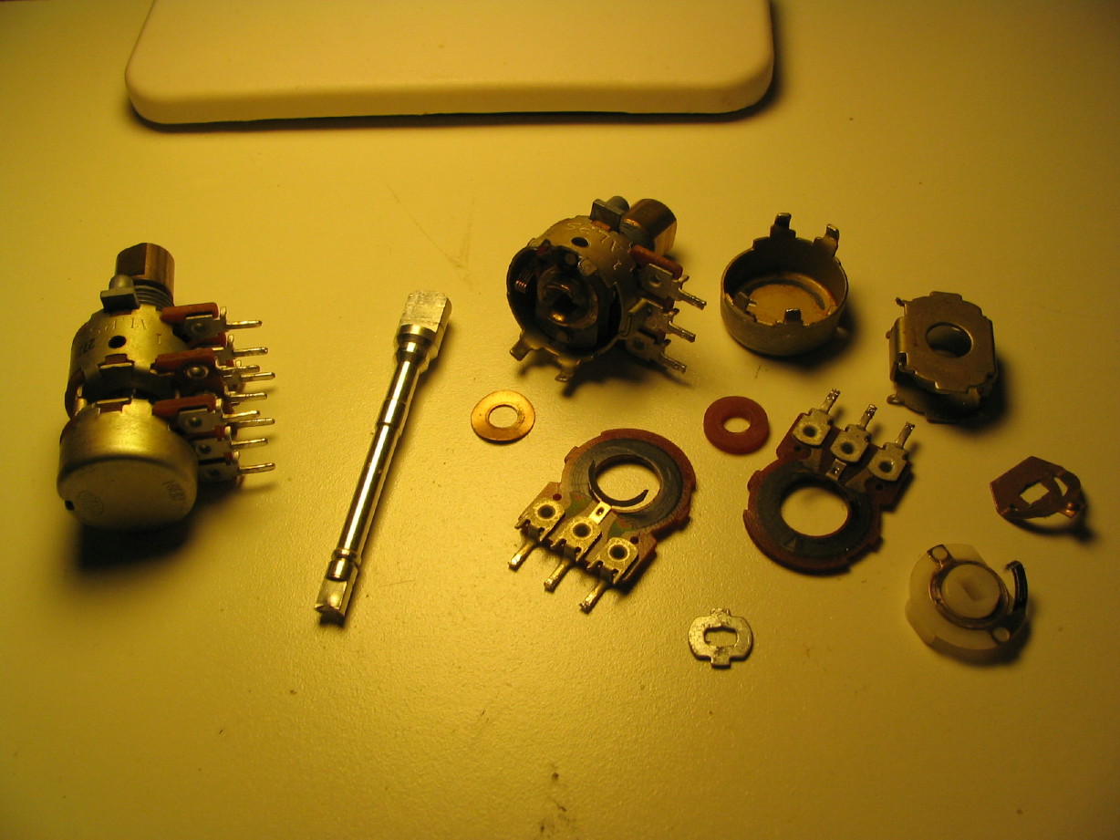
Okay...so you get the bottom of the shaft drilled and you get the wiper off...then you have to remove a little snap-ring that is on the bottom of the long pot shaft and once you do that the resistive element and the housing that connects the upper and lower pot housings coomes right off. The snap-ring is soft metal. It gets damaged when taking it off. I was able to reasonably straighten mine out, but if I was doing several of these I'd go to the hardware store and get some proper e-clips (those little e-shapped snap rings) to use when reassembling. If the original snap ring isn't straightened pretty good then it grabs and makes turning the pot yucky feeling, and who knows if little tiny peices of metal might get down into the lower pot housing...ANYWAY...So all that stuff comes off. By this time I realized that it wasn't just the long pot shaft that was bent...so was the shorter brass pot shaft. I figured out how to get that off too. I pried the tabs on the upper pot housing to get the resistive element off, and when I looked inside I could see that you can squeeze the "legs" of the short pot shaft together which unclips it and you can slide it right out the top. The straight one from the parts pot is sitting on the work-surface and you can still see the tabs of the legs in the M-___ pot that I'm holding up. Gently squeeze with needlenose pliers and pull it out:
When putting replacement shafts back in I tried to leave as much of the grease (which looked clean) on them as I'm not sure if I have the right grease on-hand.
Here is the M-___ pot in the foreground with the replacement shafts preliminarily installed. When reinstalling the short shaft you insert it into the pot housing and then gently press the double-wiper from the upper pot onto the legs until it is all the way on. Once it is all the way on you can use a tapered punch of the right size to work the legs back into the right position by just shoving it in between the shaft legs to bend the legs back.
Be careful to keep the same orientation of the wipers to the flat spot on the tops of the pot shafts or your knobs will point 180 degrees from where they used to...this probably doesn't make a lot of sense, but it will when you get into it, and I can explain it more if needed for anybody...just post a reply or PM me... Basically the wipers can go on right, or 180 degrees backwards, but the wiper has the stop on it that bumps into the pot housing which keeps the knob from spinning around and around. If the wiper is 180 degrees backward the flat spot on the top of the shafts, which orient the knob cap the right way, will also be 180 degrees off.
By the way, I gently cleaned all conductive surfaces with DeoxIT as I went. Didn't want any stray bits of metal or dirt mucking up the repair job.
So then its just a matter of putting parts back together in the order in which they came apart. Here is a picture of the repaired pot nearly all back together. I left the bottom housing off so you could see inside. If you drill the right amount off the long shaft, it will kind of snap back into the lower wiper...kind of temporarily hold itself. Then you can place the pot upside down with the top of the long shaft on a wooden workbench or wooden block or maybe even on a towel on a countertop or something (anything to keep the top of the long shaft from getting marred and to absorb a little shock) and carefully mushroom the bottom of the long shaft with a hammer. Its aluminum so it doesn't take much just to mush it a little.
Final step: put the bottom housing back on and bend them tabs back into place. I used needlenose pliers to bend the tabs back and a screwdriver to bend them out when I was disassembling.
I tested it. The upper section is rated at 20kohm, the lower at 10kohm and I measure a smooth sweep from 17kohm to 1ohm on the top and 9kohm to 1.5ohm on the bottom. That's good right?
I'm probably going to solder it back in tonight.
Phew! Might seem silly but that has really been plaguing me...what to do about it, so I'm glad it went alright, and it gives me the confidence to do it again if needed, like on the EFFECT1 return level/pan knob which is also bent...not as bad as EFFECT2, but it is possible it will snap like EFFECT2 did.
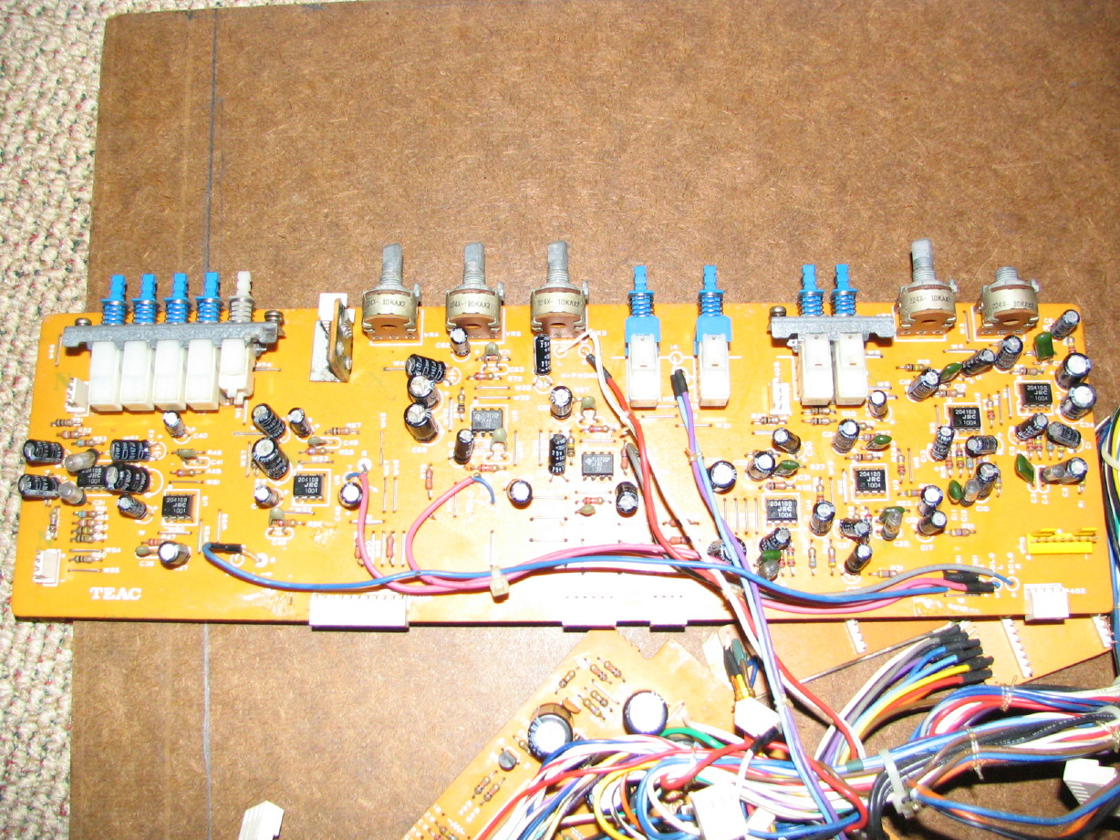
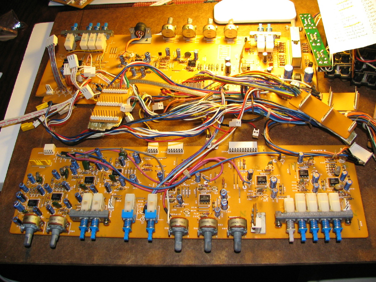
SO...all 4 Control module PCB's are cleaned, inspected and nearly completely recapped (save for 10 caps total). There are still jacks to clean and inspect, balance amp PCB's to clean, inspect and recap (though these are relatively small jobs), and some final cleanup on wiring...oh and I need to clean the knob and switch caps. But once all that is done its time to reassemble and test.
")

 :rolleyes:")


 Used to go there all the time when I worked in the machine and tool shop.


")
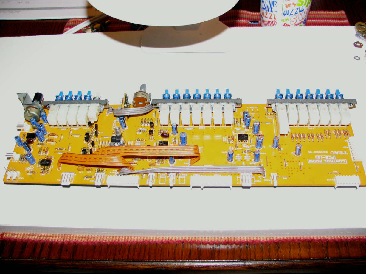
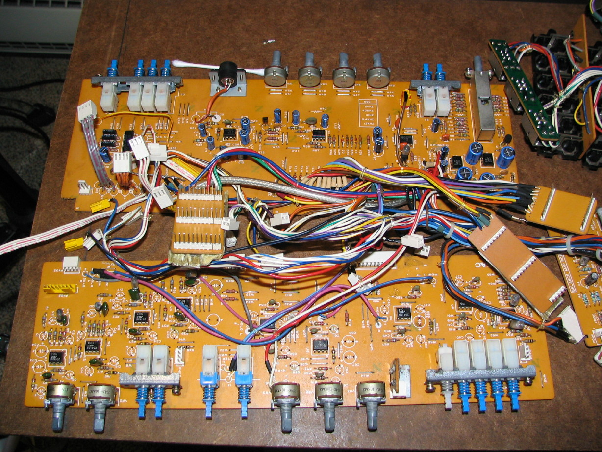
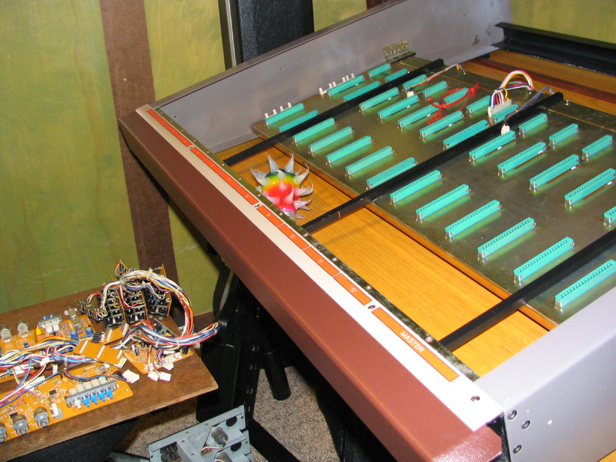
 ...really. My wife has started doing this really funny (it actually is really funny...I'm not being sarcastic) geeky laugh when I'm working on stuff and taking pictures and stuff...here it is (notice that there is a pot missing between the 2nd and 3rd switchracks...more on that below):