If the fuse is blackened and especially if the glass has crazed I suggest you do not simply replace* it. Some serious **** has take that out and you could end up with more damaged components, even blown print.
On the other hand if the fuse has just gently gone open circuit you have chances. A new fuse might restore proper operation and be fine for 'ever'. At least you might get a few minutes to find something overheating. It might just have failed due to old age!
*You need the correct type 2 amps yes but glass the fuse to find an "F" or "S" or "T" The former indictates a fast blow type S an T indicate 'slo-blo' or 'anti-surge' The vast majority of fuses are of the AS type. Often you can see a helical spring inside. Amazon should throw up several fuse 'kits' and these are well worth the few dollars they cost...will have a shufty for thee.
Oh! And on "reading schematics"? Print the fekkers out! I do.
https://www.amazon.co.uk/BOJACK-Val...keywords=20mm+fuse+kit&qid=1757076744&sr=8-28
Dave.
Nah, the fuse wasn't crazed but I am becoming. Not a slo-blo, but no letter preceding the 2A value. Just a bog-standard 2A fuse, methinks. I need to make a trip to my local hardware store anyway. They have a small electronics section. Never stocked with anything I need but I'm going anyway so I'll have a look and leave crestfallen, as usual.
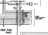
Hey so first off, yes, there are multiple 0V references, but each is specific to a power rail. Each is the 0V reference for a specific rail or rails and you’ll get false readings if you use the reference for one rail as the reference for a rail that’s not relevant. So, here are the power rails and their 0V references and the pinning on J171:
Pin 1: +6V
Pin 2: 0V (for +6V)
Pin 7: 0V (for +24V)
Pin 8: +24V
Pin 9: +15V
Pin 10: -15V
Pin 11: 0V (for +/-15V)
So, for example, you would not get an accurate measurement for DC volts across pin 2 and pin 8. Use each power rail’s 0V reference as its reference.
Regarding F501…that fuse passes power to yet another power rail. I’m not sure what the voltage is, it might be described in the theory of operation section, but regardless the rail is specific to the power mute circuit. This prevents thump in the outputs on power up. If the power mute circuit fails, depending on how it’s configured, it either allows thump to occur, or prevents audio from passing (depending on if the circuit, when energized, shunts signal to ground, and is only energized for a specific period of time during power up, or if the circuit energizes after power up to pass signal and remains energized during operation).
Many thanks and looks reassuring.
Briefly 11, 10, 9 = +/- 15vdc, great.
7, 8, = +25vdc also great
1, 2 = .6 mVdc that's millivolts, so not so great.
This is WITHOUT the fuse in circuit, got an assortment of fuses on order.
I see on the pinout for J171 mention of power mute, record mode, record signal and play mute, pins 3, 4, 5, 6, respectively. Since the fuse in question supplies power to the "power mute" function, I would assume that it DOES play a role in the correct functioning of this connector. Does that make sense to you? I will attach a photo with the connector and pinout.
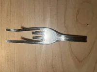
Also, for giggles, my homemade Molex connector removal tool. Sometimes they're stuck on there pretty tightly and you have to bend back two plastic tabs in a tight space at the same time to release the connector gently.
Well, I don't know if the images loaded or not. Something looks glitchy.
The fuse is not slow blow according to the service manual for USA versions.
Local auto parts stores are also a good source for those types of fuses.
Yes, that power supply for the power mute circuit and control signals and functionality do propagate over J171. And thanks for the reminder…it’s not just on power up, but also when engaging record mode.
Ok, then. I'll get a fuse in there and see what happens. I've got no lights on the VU meters either but that is also fed by J171 because, before the other failure, if J171 was unplugged, no VU lights.
Since the image won't load, a description of the "tool" I made for the Molex tabs. It's a fork. I cut the handle short, cut off the two middle tines and bashed the two outside tines flat to make tiny spatulas. That way, if I've got a stubborn one, way in the back, with the tabs facing away from me, I can just get my modified fork behind it, pry the two tabs simultaneously and the connector slides right out. They seem rather fragile so this works better than just trying to rip them out of there.