Tascam 34 - meters doing strange things

  • Thread starter Thread starter rob aylestone
  • Start date Start date
Okay. You’re welcome. Good luck.

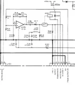
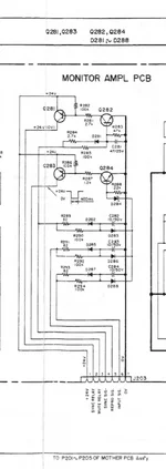
I still recommend, as a troubleshooting step, to pull the fuse for the +6V rail, and jumper the K-102 relay signal contacts on the r/p amp cards. This completely takes the mute timing circuit out of the picture and bypasses the muting relays. You’ll have thump on power up and power down so you have to be prepared for that.

And, yeah, when you posted you still had other equipment in the signal chain (your noise reduction unit), I was like (to myself) that would have been good to know. When you have a device that’s misbehaving, step one is to isolate the device as a measure of starting to sort out if the problem is related to the device itself, one or more other devices, or the interconnections between those devices. So keep that in mind when you are trying to resolve a problem or working with others in that effort.
 
Ok. I assume I DO NOT put the fuse back in after jumping the relays? Without that fuse-no VU meter lights. The Ghost in the Machine has decided for now that, ok, I can have VU meter lights but still no sound. The VU lights came back to life by magic so I'm thinking there's another batch of funky connections on the mother board. My choice is to dive into the Mother Board again (disassembly required) or jumping the relays (easier and proof-of-concept). I'm going to try the relays first just to be sure it's not a problem somewhere else and then decide if I really want to take it all apart again to check the mother board.

100% of the time I spent diagnosing and communicating with you the DX-4 WAS NOT CONNECTED. No remote control, either. Nothing extraneous. I only connected it when I believed (ha ha ha ) that the problem was fixed. It was then that I discovered that the DX-4 was not working and found the broken wire. I even tested the functionality at each stage of reassembly just to make sure I hadn't bumped or jiggled something as I wrestled this thing around on my bench. It's heavy and awkward to work on and each manoeuvre runs the risk of knocking something else out of whack.

My "day job" is saxophone repair. The skill set there comes down to being absurdly meticulous, proceeding by elimination when diagnosing a problem and NOT EVER hurrying or saying "that's probably good enough" when you have even the slightest doubt about something. My approach to this is the same, absent the concrete knowledge and experience required so I lean heavily on being meticulous and patient and striving to learn and understand as I go.
 
And just because the God of Electronic Zeitgeits wants to fuck with my head, the machine spontaneously started working again. I merely reseated the MON AMP card and, voila, music! Now, am I thrilled? No, not really. The machine is on my bench, on its back, panels off and it's butt-end chocked up with a piece of wood for easier access to the bottom. And now I'm afraid to touch it again. 40 year old connectors, wires, solder joints, PCBs and shotgunned components that prevent me from knowing what I actually fixed and what is just pure luck (or lack thereof). Absolutely confounding. I am going to leave it for 24 hours and try not to think about it and then come back and turn it on again to see what other surprises might be in store. This is just like a vintage car. You spend more time under the hood than behind the steering wheel. Crazy. I have thus far restrained myself from throwing this thing against a wall. Too heavy, anyway. Well, anyway, I'm holding off on jumping the relays for now...Having fun yet?
 
Here is hopefully the last update. It is back in its place and ready to transfer tapes. VU lights on. 4 channels playing correctly. DX-4 connected with no issues. In short, EVERYTHING seems to be working as it should. I didn't even lose any screws. I am considering this machine to be like a cancer patient. I refuse to say it is "cured". I will, however, confidently state that it is "in remission". If it is still working a year from now I will consider the treatment a success and give it a clean bill of health. Thanks again. I now have a much better understanding of the architecture of this machine. Cheers!
 
  • Like
Reactions: RFR
Hi. It's me again. Yes, I know....
Can I just jumper pins 1 & 2 on J102 to cut the mute relay out of circuit? Pin 1 goes to the relay and ground. Pin 2 goes to the other side of the relay. That's an easy job and easily reversible. And, once that's done, do I leave the fuse out or can I put it back in so I have VU lights? Schematic screenshot below.
Everything was fine for a month and then it wasn't. The patient had a relapse. There was some sort of surge, the 4 meters on the DAW went onto the red and there was a thump from the speakers. Then, no playback, back to square one. There's got to be one component that is intermittently failing.
Cheers.
 

Attachments

  • J102 and relay.webp
    J102 and relay.webp
    89.3 KB · Views: 240
That is what I suggested you do at one point as a troubleshooting measure and you said you did that and it did t make any difference so I don’t know. That’s one of the things that put me at a loss.

If you remove the fuse that will interrupt power to the lamps and the muting circuit…and anything else powered by that rail which may be nothing…I don’t know because I didn’t explore that far. The challenge here is the muting circuit is actually all throughout the unit…timing control is on the power supply PCB, logic is on the monitor PCB and the relays themselves are on each r/p amp PCB. I had also suggested you try jumpering the input and output pins of the muting relays on the r/p amp PCBs and just manage the thump with level controls to your monitor speakers. I can’t recall if you tried that and what the outcome was.
 
Yeah, no, I DIDN'T do it because the machine started working completely normally and did so for a month. God knows why. It's an intermittent problem and what I "did" amounts to poking and tweaking and dumb luck. And then this. So now I'm backtracking to jumpering the relays. There are 4 pins on the relay itself. I'm guessing two pins to activate it and two others for the actual contact. On the schematic, the two sides of the relay correspond to pins 1 & 2 on J102. It looks easier to just connect pins 1 & 2 to each other, thus defeating the relay. I just wanted you to verify that this is indeed an option. It would be much simpler and neater on the PCB to do it this way than to have to jump the relay itself (see schematic, previous post). If this does work, I will manage the thump by starting the machine and then switching amps and monitors on and then, when finished, do it all in reverse order, amps and monitors off first, machine last.
Cheers
 
So you certainly can try strapping pins 1 & 2 of J102. The only problem may be this: all you’re doing by doing that is attempting to circumvent completing the circuit to ground that energizes the muting relays coils. Electrons flow to the path of least resistance, and who knows what the actual fault is or where it is and whether or not shorting pins 1 & 2 will actually accomplish what’s desired. But you can try it. My suggestion to strap the signal input and output pins if the muting relays is the ultimate circumvention…it is the ultimate “screw you” to the whole muting circuit because it bypasses the relays altogether. So that’s the ultimate route to go if you just want to side-step the whole muting circuit.
 
I agree, who knows if it will work. Nothing to lose though. I just wanted to make sure that this was a logical way to go about it. I’ll keep you posted. Cheers.
 
Ok. I jumpered pins 1 & 2 , J102, all 4 cards. No change. Fuse in, fuse out, VU meter circuit, no difference. No "thump" on startup, VU meters static, only the usual "bounce" when turning the machine on. So that eliminates the power mute circuit as the culprit. There is hiss in the headphone amp. So, whatever is feeding the monitor outs and the headphone amp is, well, NOT feeding the monitor outs nor the headphone amp. I'm going to take the jumpers back out to bring the circuit back to normal and perhaps look further. It must be a problem further downstream from the cards where all these signals get "summed", so to speak.

The precursor to the failure (which I witnessed this time) was a disconcerting thump from the speakers (low volume, luckily) and the 4 VU meters on the DAW hitting the red. And then no playback or record monitoring. Is there a preamp circuit that feeds all of these things, monitoring on play, sync and record and the headphone amp? The symptoms point to a catastrophic failure of one component (thump, surge and then death). Or maybe a connection that is bad and arced and subsequently failed for good this time. This was an intermittent problem. It seems to be a permanent one, now. No fuses blown.
 
I wonder if I should't be looking here. All signals, repro, sync and input go through this bit.
 

Attachments

  • J203 Amp.webp
    J203 Amp.webp
    73.2 KB · Views: 232
Sorry…when you were talking about numbering pins 1 & 2 I thought we were still talking about the power supply multipin connector…didn’t double check connector references…I never suggested you jumper pins 1 & 2 of J102 on the r/p amp PCBs. Look at the schematic. Pin 1 is not connected and pin 2 is the output. So there would indeed be no change. My suggestion to you was to jumper pins 1 & 2 of the power supply output connector, which is J171. Try that. But I still think you should actually bypass the the whole muting circuit and jumper the signal input and output pins of the muting relays. Just try it on one r/p amp card.
 
So, to jumper the relay, I'm NOT going to jump the legs connected to pins 3 & 4, J102, correct? By jumpering pins 1 & 2, J102, I thought I WAS jumpering the relay. I'm still not very good at reading schematics. I'm going to go for the relays instead of messing with J171.
 
Woah, ok, I get it. L102 and K102 are in the same "box". The schematic is a bit ambiguous about that, at least for me. They're both ONE component, one end being the coil, the other end, the relay. The labelling was hidden under a wire. L102 = coil, K 102 = relay. A lot clearer now. I'm slow but stubborn.
 
Just to be absolutely sure of what I am about to do: I am going to jumper the relay from the leg that goes to R117 with the leg that goes to R164, correct? I know this may sound like a dumb question but the fewer times I mess with this, the better.
 
Did the above, J102, leg going to R117 to leg going to R164, no change. Constant hum/buzz in the headphone amp, not influenced by the headphone track volume controls at all. Global headphone volume does work. There has to be a common denominator that is preventing any signal from getting to any output. One ring to rule them all...
 
I changed the diodes on the section of the MON AMP PCB that is connected to J203, including one Zener. The machine now functions correctly, REPRO, SYNC and INPUT. No mods, no jumpers, bone stock with replaced components. I spent a lot of time trying to figure out where all of the signals converged, what they all had in common and I kept coming back to J203 on the MON AMP PCB. The clue was also the fact that the headphone channel volume controls produced no audible change in level, hiss or otherwise, when manipulated. The headphone amp was working but there was no signal to amplify. Traced it all back to the ring that rules them all, J203. So, done, I hope. Thought you might be interested as you've been helping and following this mess since day 1. Thanks to you, I've got a much better understanding of the architecture of this machine. So, Happy New Year and, well, until the next time something breaks, cheers.
 
Back
Top