Troubleshooting Hudson CS604 DO 70's analog mixer

bleachboy

Member
Hi everybody,

I recently purchased a vintage recording console, the Hudson CS 1604 DO which was made in France in the early 70's and was widely used in radio at that time. Probably most of you won't have heard about that console because it's really niche, but it's been giving me some kind trouble lately. The symptoms are very reminiscent of the issue I had in the past year with my Tascam M512, that fellow member Sweetbeats helped me fix in an incredibly generous way.

Here's what's happening :

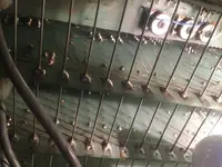
- On 5 of the 16 channels, the MIC input doesn't work. There is nothing happening on the VU meter until the GAIN knob is almost fully clockwise, at which point the OVERLOAD LED starts lightning up and the VU meter goes ballistic, he channel even outputs a very high pitched screeching noise. The LINE ins work on all channels. One of the most commonly known issues with that console is that the INSERT TRS jack input gets oxidized and shorts the connection. I have been advised to put some contact cleaner inside the plug and plugging a cable in and out of it several times. As of now, this hasn't changed anything.


Here's what I have already tried, without success :

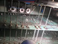
- I have replaced all of the OP amps on the faulty channels, which didn't change anything.
- Signal does come out of the INSERT jack when I plug my headphones in it, it's very faint, but it's just as faint on all the other channels.
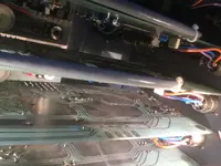
- One thing that I have done is I have unsoldered the 4 cables of the INPUT TRANSFORMER from the faulty circuit board, and switched it with the nearest channel which I know is working properly. The problem follows the transformer : the channel that didn't work previously now works perfectly, and vice-versa.

I bought the console mainly for it's input transformers which were made by a very reputable French company that built very high end transformers and microphones from the 1930's to the 1970's. That company was called "Melodium" and was responsible for one of the best ribbon microphone ever made, the Melodium 42b. It surpasses the RCA 44 in signal to noise ratio, output, and has a wider frequency response. I own two of them and they really are unreal.

My assumption is that the TRANSFORMERS are dead on all of the 5 faulty channels which really bothers me as you can imagine. But as all of my engineer friends have pointed out, it is very unlikely to blow an input transformer like that, let alone 5 !! It is very difficult if not completely impossible to find vintage replacements for these. Should I just buy replacement transformers (Neutrik makes very cheap ones https://www.thomann.de/fr/neutrik_nte_103_audio_uebertrager.htm?gclid=Cj0KCQjwj7CZBhDHARIsAPPWv3dmVU6tDdBysO4AJWlQsQiRPptuPvUfV2O4SoyMsiSnf4Z1Zk2p7LAaArShEALw_wcB but I guess they won't sound the same at all...).

How should I test the transformers ? Is there a way to know right away if they work or not by using a multimeter ? This is pretty much the only measuring tool that I have, and I really don't know how to use it properly.

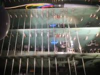
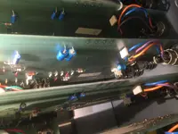
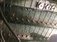
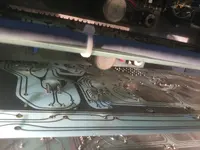
Is there a step that I might be missing ? Something other than the transformer which might be the issue here ? The console is very hard to work on, all of the busses are hard wired, I would have to desolder everything to have access to one channel card...I have had a quick look at the electrolytic capacitors, which all seem fine to the naked eye, but then again that may not mean they are functioning properly.

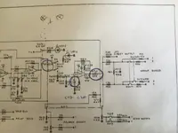
What are your thoughts on this ? I have attached the schematics of the console.

Thanks very much.

Louis
 

Attachments

  • HUDSON SCHEMA 2.pdf
    3.8 MB · Views: 5
  • HUDSON SCHEMA.pdf
    643.1 KB · Views: 4
Last edited:
I think that’s more mid 1970s era based on the construction and the opamps used versus early 1970s. The 4558 wasn’t even introduced until 1974.

Anyway, you need to stop shotgunning parts and do some real troubleshooting to nail down what the problem is, because otherwise you may be creating new problems while not fixing the original problem and now you’re chasing your tail. I realize that’s what your post is all about, an ask for some help with logistical troubleshooting. So let’s do some. BTW it is not common for a transformer to fail unless it has been physically damaged. You can use your multimeter to measure resistance between the primary wires and the secondary wire. The primaries are the input wires of the transformer that connect to the input pins of the XLR jack. The secondary is the signal output of the transformer. In your console the secondary is the wire that connects to the MIC/LINE switch. So measure the resistance between each primary and the secondary. Do this with a transformer from a known bad channel and compare to a transformer from a know. Good channel. If the measurements are essentially the same, the transformer is not your problem.

Another thing…the schematic shows the XLR wiring is pins 1 & 2 signal, pin 3 ground. That is weird-ass wiring. Pin 1 should be ground, and pins 2 & 3 signal. Just be aware of that. I don’t know if it is a misprint in the schematics, but I don’t know if any mic that has pin 3 as ground. So check the wiring of each XLR jack and see if maybe somebody modified all but 5 channels to be the standard pin 1 ground, and your non-functional channels just need the XLR jack re-wired, or if they are all pin 1 ground and the schematics are in error.

If the transformers are all good, and the XLR wiring is okay, then let’s work on the next thing…You said you can hear signal out of the insert jack. But it’s faint. And you’re using your headphones. Don’t use your headphones. Get a proper insert cable and plug the send cable into a legitimate way to monitor. And if you don’t have a proper insert cable and can’t make one, buy one. If you want to fix it, let’s correctly troubleshoot it. I want you to do a couple things with a known faulty input strip:

1. Connect a dynamic mic to the mic input, select the mic input as the source, and set the GAIN to where the clip LED is just flickering on peak levels.

2. Leave the EQ section switched out or OFF.

3. Raise the channel fader to unity gain.

4. Connect the direct output for the channel you’re testing to your monitor speakers/amp/headphone amp…whatever you use to monitor output. If all you have is headphones, go get something that can appropriately monitor a line level output, unless you have a headphone amp with a line level input…then you can use that and connect your headphones to that.

5. Do you have appropriate signal? I’m guessing not. But let me know. If not…

6. Connect an insert cable to the insert jack with the same settings as above, and connect the send plug of the insert cable (or actually it looks like maybe the tip of the TRS insert jack is the send conductor, so you could in theory, if I’m reading that right, connect a standard TS cable to the insert jack to get the “send” signal) and connect that to your monitor setup…anything?

That’s all I want to know for the moment.

General comment…you said the electrolytic capacitors look fine to the naked eye. That tells you nothing. Yes, sometimes the failure state of an electrolytic capacitor presents as bulging and/or leaking of the electrolyte. I think more commonly the electrolyte, after decades (and your console is over 45 years old now), just dries up. The cap looks normal but the electrolyte is either gone or significantly diminished and the cap won’t work as it should in the circuit, if at all. Do the tests above and report back and we’ll go from there.
 
Hello again,

I have first checked the wiring of the XLRs, they are all the same on each channel.
I have then tried to measure the transformer wires with the multimeter, and here's what I have : there is 1 red wire and 1 green wire that connect to the PAD switch. I've put each of the multimeter's probes on each of those cables, set it to OHMS (2k) and the reading is the same on each transformer, between 22,0 and 24,0. However, I get no reading at all on any channel when putting one probe on either the red or green cable and the other probe on the black (ground ?) and blue cable that connects to the MIC/LINE switch, which would be the secondary winding of the XFORMER.

As for further testing, I've made a quick video which may clarify the issue a bit :
I have tested the direct outs with a TS jack plugged into my Yamaha HS5 powered speaker. They work on good channels, but don't work on faulty channels. I have also tested plugging a male TRS to 2 x female TS Y cable into the INSERT jack of the console, and connecting either the RING or TIP female jacks into the speaker, without any sound on those faulty channels.

Hope this helps the troubleshooting a bit, I myself am completely out of ideas !
 
I don’t know what I’m was thinking…ignore my crackpot advice to measure resistance between the primary and secondary wires of the transformer. You can’t do that. It will always read open circuit. But you can measure the resistance across the primary coil (red and green wires) and measure resistance across the secondary coil (blue and black wires). If those are all about the same (if the primary coils all measure about the same and the secondary coils all measure about the same, and don’t worry if the primary coil average is different than the secondary…that’s fine), then that’s a good indicator the transformers are fine…no open coils. You can verify by injecting tone at the primaries of each (via the mic jack is fine, with PAD switched in) and then looking at the output at the blue wire with a scope and you should have clean tone there.

XLR wiring is all the same? Okay good. But what is it? Does pin 1 go to ground and pins 2 & 3 go to the primary coil of the transformer?

Thanks for the video. That helps paint the picture of your problem. So in the video that meter is one of the group meters, yes? The meter peaks but there is no sound? And you have no sound at the send contact of the INSERT jack, right?

Patch the INSERT send of a bad channel to the LINE input of a good channel. Assign the good channel to a group channel. Does the group meter do the same thing when you adjust the MIC TRIM as it does when the bad channel is directly assigned to a group as in the video?
 
I've made 3 videos where I go through the steps you've mentionned :


Pin 1 goes to ground on all channels, pins 2 & 3 are indeed connected to the primary coils of the transformer (the red and green wires that are connected to the PAD switch).

Primary coil readings :
0,22 on each channel, even bad channels.
Secondary coil readings :
1200 on all channels except the bad ones. There it's reading just 1 on the MM.

Yes in my previous video the meter is the meter for group 3. Meter peaks without sound, except a loud and very high pitched feedback when the gain is at full. The VU doesn't respond to the microphone, only to the gain pot when it's on full.

I get the same results/same sound when an amplified speaker is connected to the SEND of the insert jack. Same thing when using the direct out.
 
EDIT : When doing the same test with channel 5, the VU meter sort of reacts to the MIC input (the louder I talk the higher it shows on the VU), however the sound I get is much quieter than on other channels and there is a lot of background hiss on the output. When I set the gain at full, it does the same as on the other bad channels, which is : VU goes immediately full on red and stays there, same with the Overload LED. It does not do that gradually, it goes directly from almost 0 to 100 % from a light touch of the GAIN knob.

EDIT 2 : the MID EQ problem that I mentionned in one of the videos is now fixed after replacing IC 2 and 3.
 
Since I'm getting the same reading when measuring the BAD secondary coils' black and blue cables as when the MM is on without the probes touching, I assume there's an open coil on the secondary of that transformer.
 
Since I'm getting the same reading when measuring the BAD secondary coils' black and blue cables as when the MM is on without the probes touching, I assume there's an open coil on the secondary of that transformer.
Yes I believe that’s correct. One thing that confuses me though is I thought you said you swapped in a transformer from a functioning channel to a non-functioning channel and it didn’t make any difference. Is that correct?

Regardless it sounds like you have some transformers with open secondaries which is odd, but would definitely create a problem.

You may have multiple issues going on with your non functioning channels.
No actually it's the other way around : when switching transformers, the issue followed the transformers : bad transformers soldered in good channels = no sound; good transformers soldered in bad channels = good sound.
 
After swapping the bad transformers, everything started working again ! It would have been so simple to close the lid and patch the console but noo I had to change all the 300 electrolytic capacitors first…which I did…now I have :
- channel 7 receiving signal but not sending any output to the busses. I do have sound on the « solo » bus and movement on the solo Vu meter. I also have signal on the INSERT return. I’ve tried to follow the schematic, to pinpoint the exact location of the problem without success. I’ve checked all of the soldering on the newly replaced capacitors, no issues. I’ve swapped all of them, same problem. I’ve also swapped all of the Op Amps, same problem.

- on channel 13, for some reason, I have a much higher signal than on any other channel. I have no idea why. It sounds good, it’s just 10 db louder than all of the other channels, on MIC and LINE inputs. Could it be a bad resistor ?

I should never have started all of that mess 🤯
 
Slow your roll on shot-gunning parts. You’ve gotta proceed slowly and with some basis in logic rather than the scatter-gun approach because the scatter-gun involves risk in creating new damage and then you’re chasing your tail. It’s best to do kind of one thing at a time if you can because if you don’t, you don’t know what you did that caused the problem and reasonable deduction is part of the troubleshooting; hard to deduce when there are multiple culprits.

At some point you’re going to have to get out the tone generator and oscilloscope or at least a good DMM and start tracing I think. But there’s still a couple things to do before you get to that to narrow it down.

Channel 7: can you get signal to the ECHO or FOLDBACK busses? How about at the DIRECT OUT jack? I assume you removed the input PCBs for repairs and recapping right? Can you post some pics of the guts, so we can see how the input strips interface with the output section? If you took the PCBs out consider all the stuff you disconnected and possible damaged solder joints or connections, etc.

Channel 13 we’ll just need to come back to that. Could be a bad opamp. I think we should focus on one thing at a time.
 
Thanks again. I know…shouldn’t have even attempted the recap at all. I still managed to get 14 channels working out of 16, replaced 4 transformers and 4 potentiometers which were mounted from the underside of the PCB and almost impossible to find, which is not so bad after all for a complete beginner…at least that’s what I’m telling myself to prevent me from throwing the console to the trash !! On the channels that do work though, the sound is way better than it was before the recap, especially the EQ.

One thing that could have happened during the recap is that maybe some of the PCB traces got scratched, possibly breaking some connection somewhere. The thing is, all of the channels are hard-wired to the busses, so I didn’t take out the channel PCBs, I did all of the « repairs » with the cards still wired, from the underside of the console.

Channel 7 : basically, signal’s definitely coming in (MIC or LINE), but not coming out. I can’t get signal out of the DIRECT OUT, nor to either of the 4 main groups. However, I’m getting a faint signal on the INSERT RTN. I have signal coming out of the FOLDBACK, but not of the ECHO jack. So if I am reading the schematics correctly, my problem should be located somewhere between C15 and C20 right ? Since the ECHO bus, GROUP busses and DIRECT OUT come right after the FOLDBACK busses. And C17 / C20 are two electrolytic capacitors that I have replaced, so I’m guessing something might be wrong around one of those solder joints, what do you think ? But I already have put back the old C15/C17/C20 capacitors and the issue still remains. So the problem might be close to those 3 parts, but I don’t think that any of those 3 capacitors might be at fault here, since replacing those didn’t make a difference.

I will try and take as many pictures as I can of the channel cards, but as I said, all 16 PCBs are still hard wired together so the pics might not help that much.

All in all I’m convinced that both of these issues might be very simple to fix, I just don’t know how. Might be just a bad solder joint, some other part that was moved just a little bit but the connection is broken somewhere. I’m hoping it’s not a scratch on the PCB traces that’s causing that.
 

Attachments

  • C44C6EDC-5984-4B9B-8F28-BBD938BB2FA1.jpeg
    C44C6EDC-5984-4B9B-8F28-BBD938BB2FA1.jpeg
    2.1 MB · Views: 2
Here are a couple of pics of channel 7, I really hope they can be helpful.
 

Attachments

  • A1C62093-DC41-48A4-8045-7D3C7024B0CB.jpeg
    A1C62093-DC41-48A4-8045-7D3C7024B0CB.jpeg
    1.9 MB · Views: 9
  • 01D588A1-02D7-4305-8977-BE3D720B7A4B.jpeg
    01D588A1-02D7-4305-8977-BE3D720B7A4B.jpeg
    1.8 MB · Views: 7
  • EB1972F3-3C05-460B-9E7A-EAAA5E5980CD.jpeg
    EB1972F3-3C05-460B-9E7A-EAAA5E5980CD.jpeg
    1.7 MB · Views: 7
  • B3CA8279-0456-453D-9904-8ACE71732DA6.jpeg
    B3CA8279-0456-453D-9904-8ACE71732DA6.jpeg
    2.2 MB · Views: 7
  • 78C7FF9D-B882-4116-AAC0-42E1A88FBDBF.jpeg
    78C7FF9D-B882-4116-AAC0-42E1A88FBDBF.jpeg
    2 MB · Views: 6
  • E55E6BC1-3A34-4ADE-87D1-F3A049110EED.jpeg
    E55E6BC1-3A34-4ADE-87D1-F3A049110EED.jpeg
    2 MB · Views: 5
  • DA8568A8-AA3F-495B-B807-EAAAB84CD6CE.jpeg
    DA8568A8-AA3F-495B-B807-EAAAB84CD6CE.jpeg
    2 MB · Views: 6
  • 9401613C-1613-423B-AE3B-5E8A86CDA326.jpeg
    9401613C-1613-423B-AE3B-5E8A86CDA326.jpeg
    1.9 MB · Views: 6
  • D4B482A4-6F60-4DE9-A87E-9AE3BB6D0CC8.jpeg
    D4B482A4-6F60-4DE9-A87E-9AE3BB6D0CC8.jpeg
    2 MB · Views: 8
You have such a random approach and if you are struggling with a test meter then your real faults are possibly going unfixed. One of the cards that works is the key. A set of measures results that you can use to identify a good board. Then the faulty board to compare to. You have to be methodical and follow a system. How many good bits have been removed and replaced with others? I don’t think we have a clue from the pics as you’ve steamed in big time with unnecessary ‘fixes’ measure some good boards and the faulty ones and then you’ll know where to look?
 
I understand that…trouble is it would be much easier to test the boards if I could just take them off the chassis individually without having to desolder everything that’s hard wired, but I really don’t have the confidence to do that as it will most likely create more problems
 
Yes - that's always the pain with soldered in boards. Your original faults probably seemed like transformer faults, but I've never lost a transformer other than though damage. I's bet power supply issues were key here. Probably through old dry joints. Old capacitors that fail in audio circuits usually cause noise first, but sometimes instability.

A meter tests voltage and continuity, but really for audio repair you do need test gear. A signal generator to inject say a .5v audio tone, then a scope so you can follow it and see it's progress. You can see distortion and measure the voltages and when you compare channel to channel can pick up very small changes. They let you leave the boards in and powered. However, that's probably a 300 quid investment for something you will never do again, and you have to learn how to do it, too! Most cheap meters cannot display audio voltages - so they're a bit rubbish for this kind of thing really!
 
Here is a YouTube link of a short video that I’ve just made, it’s silly really, but wiggling the channel 7 card actually gives me signal…! It seems it’s the way the channel itself is soldered to the buss wires that gives me trouble…

Youtube link : Hudson Channel 7
 
Last edited:
Back
Top