So I remember now why I was kind of dreading the 16-track system harness installation project...there's a whole bunch of other stuff kind of tied to the process...like opening a pandora's box...or starting any home plumbing project...it just kind of keeps going.
Putting the 16-track system harness in means finally dealing with upgrading the cooling fans from traditional 120VAC Muffin fans to a pair of super quiet (and higher CFM) 12VDC computer case fans wired in series and powered off the 24VDC transport power supply; it means dealing with some janky wiring associated with the remote connector on the 16-track harness...the harness came off of a machine from Fantasy Studios that had some secondary remote system, and there's this chunk of wire that's been spliced in. My thumb and 3rd and 4th fingers are holding the factory Winchester remote connector, and the 1st and 2nd fingers are holding and pointing to the chunk of wire:

It means replacing the power panel in the front with the later model version that has the 120VAC power outlet and brake release pedal connector...I'm holding the panel-to-be:

It means replacing the 10' or so of 3-conductor 12AWG stranded wire that carries the mains power from the power socket in the back of the machine to the power panel in the front...after 40+ years the insulation is crumbling:

And it means having to make some tough decisions...one of the connections on the back of the 440B/MM-1000 amplifier electronics carries record lamp power to the control panel and to the remote, and it also handles auto-source switching on later models. My MM-1000, being an early model, does not have the auto-source or "auto-input" switching functionality, and the original harness in the machine was appropriately lacking the conductors for that functionality. Well, the donor harness *has* all that wiring, so that if at some point in the future I want to add that functionality (I have schematics for the additional guts in the electronics so I could add the components), the "new" harness would allow for that. Right. But the issue is that the connector on the back of the electronics is
normally a 4-pin Cinch Jones connector. Mine has a 4-pin circular Cannon connector. Why? I don't know. Could be my electronics are very early 440B/MM-1000 electronics and they hadn't settled on what they were using yet? There are some other elements of my machine that make it a very, very early MM-1000, so this hypothesis is plausible. So the *question* is, since my electronics have the Cannon connectors, and the incoming harness has the Cinch Jones connectors, do I replace the Cannon panel-mount connectors in the electronics with Cinch Jones, or hack the harness and swap in the cable-mount Cannon connectors from the original harness? So that's another issue with which to contend in the harness swap.
Out of the box comes the pile of spaghetti...the cassette is for reference:

There's so much wire in this thing...here's a shot through the front lower left rack at the harnessing *just* for the audio cabling to and from the two 8-channel sync relay modules:

So to work I went. Getting the original harness out from the lower section wasn't too bad...there are a number of screw-mount type zip ties that anchor the harness to the chassis in strategic locations...I just clipped those as I have new ones to go in. So I unplugged it from everything (control panel, transport, power supplies, relay box), clip-clip-clip, etc., removed the channel 1~8 electronics power supplies so I could extract the power to the fans, and unmount the power socket from the back panel...and unmounted the power panel. Then it was time to go to the upper racks...this was where I was apprehensive as I really didn't know how easy it was going to be. A quick look and I thought "Oh cool! I just have to remove the top level of electronics modules and I can clip the zip ties and hopefully feed it through the chassis!" Out come modules 1 and 2:

So I go to start working the harness out from in between the remaining modules and...shoot...more zip ties...
unplug-unplug-unplug-unscrew-unscrew...

NOW were in business...wait...arg...


...okay...NOW we really are in business.
So I was worried about trying to feed the mess through the overbridge upright, because some of the connectors are a tight fit. Well, its pretty cool...there's an inside cover panel that comes out SO easy. Its basically held in by spring tension from the way the panel is formed. There's a screw and a nut at the top that prevents it from sliding down. Remove those, slide it up so you can kick out the bottom...

And then you can slide it down far enough so the top clears and out it comes. Here you can see the end of the panel and the "wings" that keep the panel in place when its installed:

So with that out it was much easier to finagle the whole mess through from the top down to the lower chassis...*poof*! Its out:

So last night I got the new zip ties installed in the overbridge, and called it a night. I picked up new cabling to replace the internal power cable, so the next steps are to finish replacing the screw-mount zip ties, and replace the power cable on the harness. Then I need to re-work the fan power leads, and figure out what I'm doing with the 4-pin connectors for the overbridge...Cannon or Cinch Jones. Anyway, the last shot from last night showing new zip ties:

I saw a photo of your studio setup (with Matilda) a few pages back (page 79
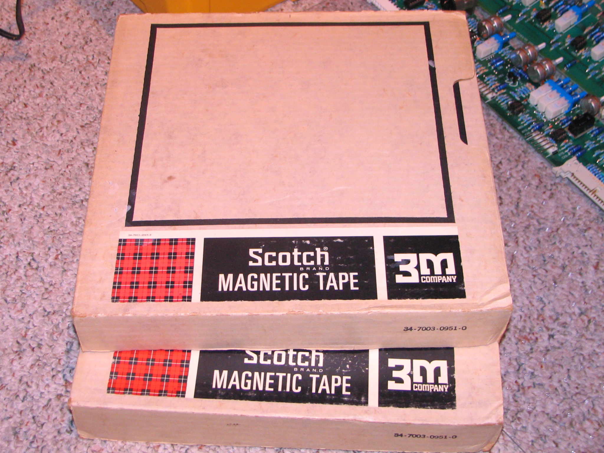
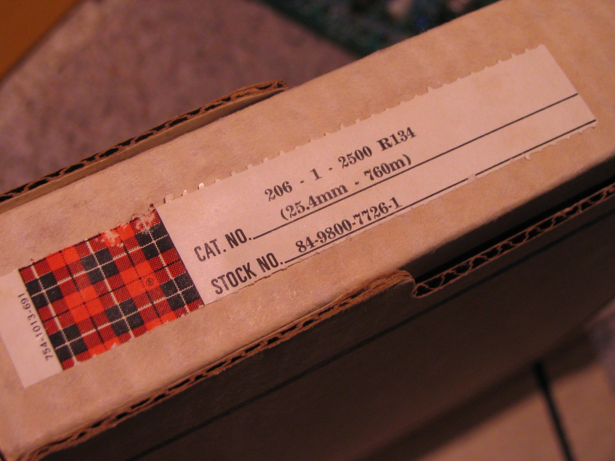
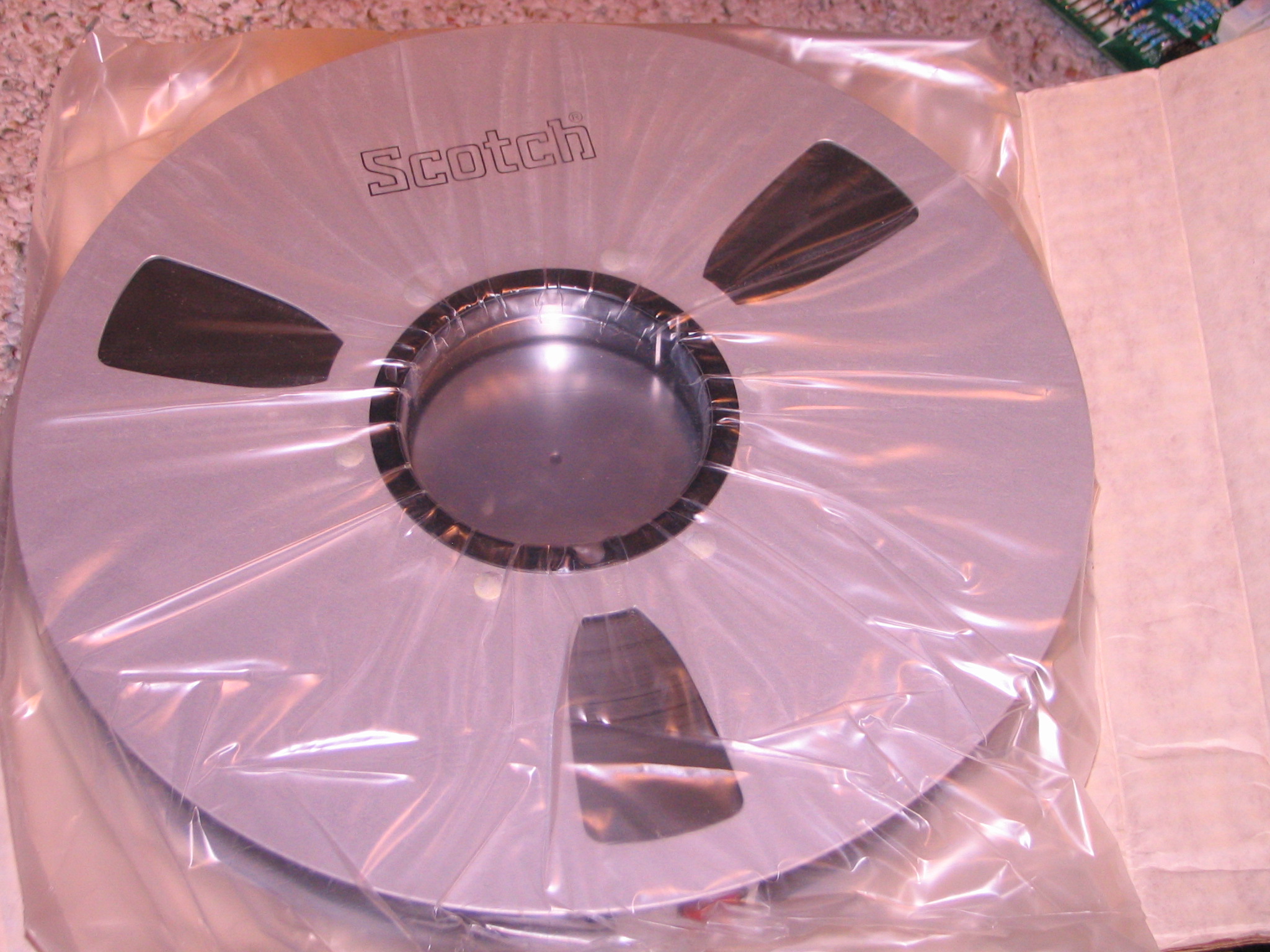
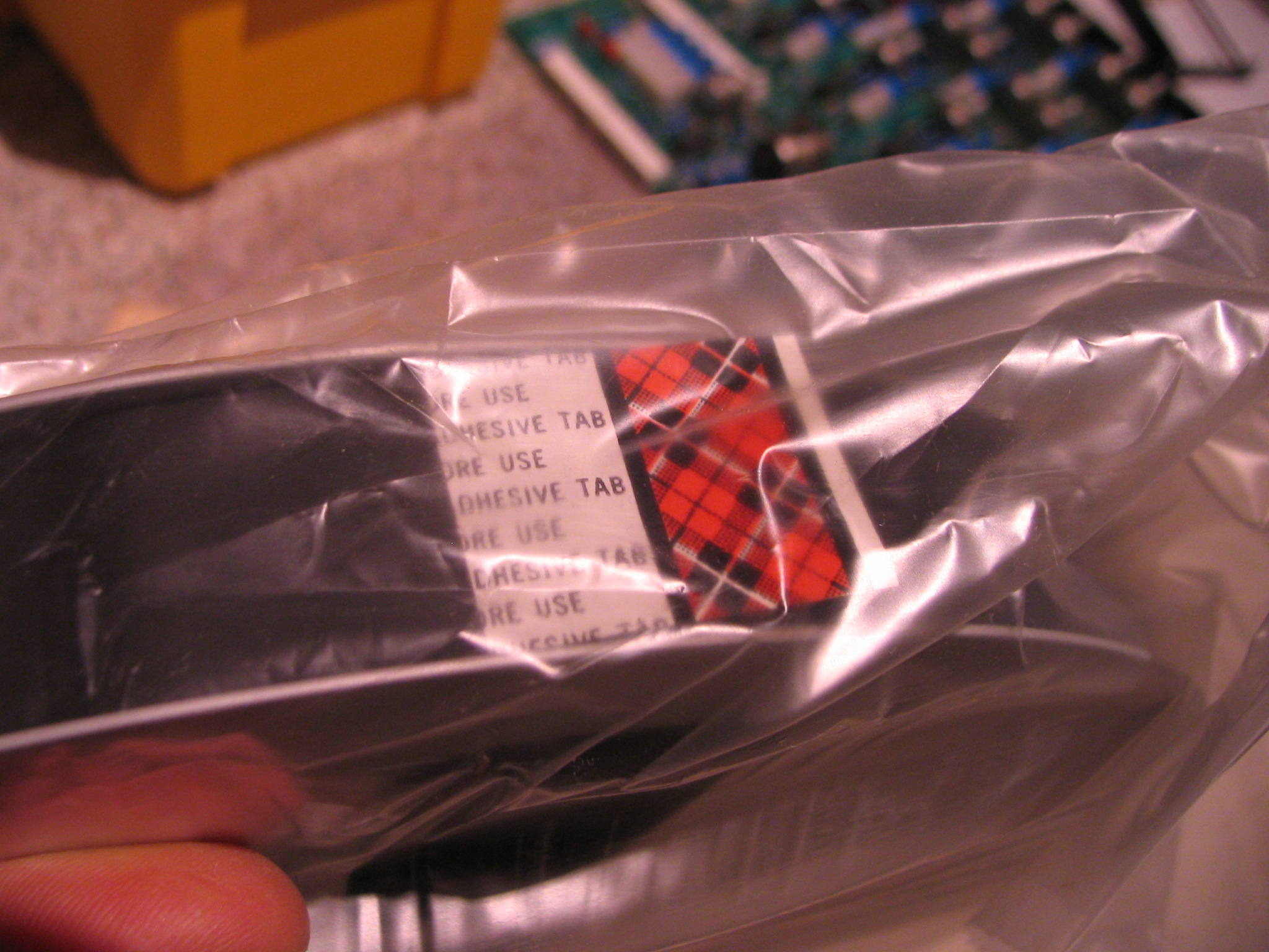
Really nice setup and I can sense that you're enjoying the fruits of your labor. Nice going, really. It's good to see that you haven't lost your passion for this stuff. Have you ever considered going for a "dub" sound using old dynamic mics and gritty sounding tape, from the late 60's, early 70's? Sometimes you can find nice Scotch 206 in wide format. It would sound awesome on your machine.