Tascam M520 Story...

  • Thread starter Thread starter sweetbeats
  • Start date Start date
...

Make sure all the 2p jumper plugs are installed on the back. There are jumpers for channels as well as busses. Well over 20, but I forgot exactly how many. Any jumper plug that's missing from it's associated jacks will create a breakpoint in the signal. People would often remove these plugs to facilitate patching of effects inline or creative routing of the signal offboard.:eek:;)
 
There are 28 total.

Good point, Dave, but that wouldn't effect one side of the MONITOR sum being out...

Do make sure of what A Reel Person is saying though onesong. At the top of each channels jack set is a ACCESS pair of jacks...basically the insert for the channel on two RCA jacks being labeled SEND and RCV. The PGM groups have ACCESS jacks too. That's what makes it 28 jumpers. 1 for each of 20 channels on the M-520 and 1 for each of 8 PGM groups.
 
I hooked up the monitors to the PGM outs like you said. They work perfectly that way. I exercised the switches on the monitor select like you said; no change.

Also, all the jumpers are in the right places. The guy I bought the board from actually even gave me two extras just in case.

I double checked through the headphones too, just to see. Same issues (no surprise there, just did it and wanted to include that.)

Thanks for all the help, you guys are brilliant.
 
Okay.

Let's individually try all the different sources you can select in the MONITOR SELECT switchrack and make sure they output both channels to the STEREO A, STEREO B and headphone jacks. This will help narrow down where the problem may be.

So, for instance, hook your stereo DAW output to the 2 TRACK A and B inputs (I think you did that already but I want to confirm) and select each on individually in the switchrack and test the output.

Try the same thing with the SPARE input jacks.

Now hook the DAW output to two TAPE IN jacks on any two channels, source those to the AUX 1-2 buss, raise the AUX 1 and 2 faders and source AUX 1-2 in the MONITOR SELECT switchrack.

Now try the same thing with AUX 3-4.

Now source those tape jacks in the MONITOR mixer and see if you get both channels when you select MON in the switchrack.

Lastly, one more time, route the channels to which you have the DAW output connected to the tape jacks to a pair of PGM groups, source those BUSSes in the MONITOR mixer, and select MON in the switchrack...just one side?

What happens now when you latch the MONO switch in the switchrack?

Try all these things and post back with detailed results.

Let me know if yo have questions about these instructions.
 
tried both 2track inputs: work when selected on the stereo master out switchrack through both stereo master outs.

both channels through both stereo master outs when plugged into the SPARE and it is selected on the switchrack

both channels when ran through Aux 1/2 and 3/4 from any channel's tape inputs.

same thing when setting the monitor channels to corresponding tape ins.

When run through the monitor mixer and the MONO button is depressed, the mix plays out of both speakers in mono; still no left side when in stereo.

Here's an interesting note: no matter how I route the DAW, it always only comes out of the right side of the headphones. Even when the MONO button is pressed. the only time any sound comes out of the left side of the headphones is if I have the SOLO button pressed on the channels when they are set to use the Tape In inputs.
 
Last edited:
:eek::eek::eek:

I'm focusing on the issue of the monitor mixer outputting only the L channel when sourcing the PGM groups for now...that R channel only in the headphones thingy is going to have to wait...your issues are not simple. :(

First, let me make sure I've got this right, and then after that I've got some questions for you...

Okay...(deep breath) You can monitor TAPE jacks through the monitor mixer and you get both channels of the monitor mixer sum to the STEREO A and B busses right? The only button in the MONITOR SELECT switchrack that is depressed is the MON switch...have I got that right?

Then, leaving everything else the same, if you route those same TAPE jack sources to, say, PGM groups 1 & 2 (***and leave them panned center on the channel strips***), raise the PGM 1 & 2 faders to unity and flip the source select switches for monitor mixer channels 1 & 2 to BUSS, leave them panned center, raise the LEVEL knobs and all you get in the STEREO A and B outjacks is the left channel? And then if you turn off the monitor mixer channels 1 & 2 (so they are set to the center "l" mark) and flip the monitor mixer channels 9 & 10 source select switches to BUSS, leave them panned center and raise the LEVEL knobs its the same thing? Only the L channel comes out of the STEREO A & B out jacks?

Kuh-razy.

Tell us more about the board...

  • Do you know of any damage it has sustained?
  • Carefully inspect the exterior of the mixer...any major scratches/dents/dings?
  • Have you opened up the top panel and looked inside at the motherboard to see if it appears that liquid was ever spilled on it? (1. remove connections from the jack panel; 2. remove the six black philips screws located along the width of the mixer just above the channel and master modules; 3. tip the entire meter bridge/top panel/jack panel back; 4. get a good flashlight and have a look inside...how's it look??)
  • how was the mixer transported to you?
  • have you contacted the previous owner to ask about this issue (i.e. can they give you any insight as to what might be causing the ill behavior)?
 
I must have worded something wrong. I'm sorry if I've confused you. I never hear ANYTHING in the left channel, unless I plug the DAW into the Stereo Tape Return A or B and select Stereo Tape Return A or B on the MONITOR SELECT switch rack.

If I run it into a tape in on normal channels, say 1 and 2, I and select TAPE on the corresponding monitor channels, I still do not hear a left channel. If I press the MONO switch, the left speaker will come on, but it is a mono signal. I can press the SOLO button and hear the left channel, however.

The same goes for the PGM busses. no matter what I plug the DAW into, if I select bus 1/2 or 9/10 or any others, I never get anything out of the left speaker, that is, unless I press the MONO button and get a mono signal, or press SOLO on the channels I'm plugged into.

There are no signs of any physical damage, scratches, dents or dings. I've seen nothing to indicate any liquid being spilt, I will double-check. The guy I bought it from had only used it's inputs through the direct outs; he always monitored out of his DAW....oh the downsides of digital.

I brought it home myself in my car. I have a big trunk and I padded it up with foam and blankets.
 
Yes. I was confused:

both channels when ran through Aux 1/2 and 3/4 from any channel's tape inputs.

same thing when setting the monitor channels to corresponding tape ins.

Sounds like you are saying you get both channels out of the monitor mixer when sourcing TAPE jacks. I see now you are saying that the "same thing" occurs when sourcing TAPE jacks as when sourcing the BUSS.

I'm actually glad it happens when sourcing the TAPE jacks as when sourcing the BUSS. It would be a real mind-bender if not an impossibility if it were the way I was assuming which is why I started my last post with ":eek::eek::eek:". :D

So do I have this right...I'm putting a list below of each function on the MONITOR SELECT switchrack and the result when used:

MON - right channel only
SPARE - works
2TR A - works
2TR B - works
AUX 1-2 - works
AUX 2-4 - works

Is that right?

What happens when you connect your DAW output to the "MON" jacks in the "SUB IN" section of the master jack bay (the ones right above the "SPARE" jacks)? I'm hoping the answer is "no left channel".

Bottom line (if I got the above correct):

I don't know how comfortable you are tearing things apart but my assumption at this point is that you've got a bad connection between the MONITOR (B) PCB and the MONITOR SELECT switchrack PCB (output from the monitor mixer is hardwired to the MONITOR (B) PCB and comes to the switchrack on connector P3). You might try removing that connector from the MONITOR (B) PCB and working it with some DeoxIT...also could be a bad MON switch in the switchrack or possible R1 or R2 on the switchrack PCB (which Teac calls SW E PCB)...worst case scenario is a blown opamp, bad capacitor, resistor or solder joint associated with U7 in the MONITOR (B) PCB. If it were me (after checking out the switchrack and finding no solution there) I'd be pulling the MONITOR (B) PCB out and looking at U7 and its associated components. looking for scorching or a bad connection to start and then desoldering caps and resistors and testing...It could be a simple oxidized connection, or some deeper issue but it is all diagnosable and solvable.
 

Attachments

  • U7.webp
    U7.webp
    47.4 KB · Views: 212
Last edited:
Cory,

I'm here. Just a heads up. The mailman just delivered the 1" reel. It is in amazing condition. I am so glad that you offered that for sale. Thanks for the fast shipping too.

Regards,

Danny


And now back to your regularly scheduled progamming.
 
Very cool! :D

I'm very pleased you are pleased! :p

Its gonna look nice on yer MS16... ;)
 
Sorry man, I was out for the weekend.

I just hooked it up to the MON ins on the back......I do get both channels! This is so confusing....any ideas what that means?
 
Just to confirm...you have tested all of the monitor mixer channels right? I mean for instance plugged a source one-at-a-time into tape jacks 1 ~ 16 and tested each monitor channel 1 ~ 16 to see if it outputs both or only the right channel?

Do that and post back.

I can explain the possible problem area schematically but I want to confirm for sure that the problem occurs with each and every monitor mixer channel to avoid a wild goose chase.
 
I checked every monitor channel like you said, I only ever hear the right channel on any combination of monitors.
 
Okay...thanks for doing that.

Okay. The tape returns and the PGM groups come into the Monitor A PCB's (the 8 PCB's that have all the LEVEL and PAN knobs for the monitor mixer...the first card has the channel 1 and 9 pots, the second has channels 2 and 10 all the way to the last one at the right of the mixer with 8 and 16) and they all get combined into one 3-conductor wire with R, L and ground that goes to the Monitor B PCB (one PCB...it has the actual amplifiers to get the monitor mixer sum to all its places). At this point we can assume that the circuitry on the Monitor B PCB is okay. That's what we were testing when I had you see if you got only the R channel or both R and L when connecting your DAW to the MON SUB IN jacks...you see, those jacks daisy chain right on to the same place as the output sum from all the Monitor A PCB's...I hope that makes sense. On the Monitor B PCB, if neither the output from the Monitor A PCB array or the MON SUB IN jacks worked then I'd be doing what I said eairlier about checking the monitor select switchrack PCB and U7 on the Monitor B PCB. But since the MON SUB IN jacks work we know that the Monitor B PCB and MON section of the MONITOR SELECT switchrack is working okay. That's good news AFAIC.

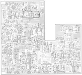
So the problem is further upstream than the Monitor B PCB, and my top suspect is that 3-conductor wire from the monitor mixer channel 1/9 PCB. There is a picture of the left side of the channel 1/9 PCB below, and the connector would be on the right side of the card (left and right as it sits in the mixer). The connection is labeled "P3". What you are probably going to have to do to do this right is get to that conection to inspect it, seat and reseat it a couple times applying contact cleaner like DeoxIT. To do that you'll need to:

  1. First, always-always-always disconnect the power supply from the mains power, and then switch the power supply on for a few minutes to discharge the electronics.
  2. Tip the meter bridge/jack panel assembly back like I described earlier and find a way to safely prop it open.
  3. Remove the trim strip between the armrest and faders (also 6 screws)
  4. With the meter bridge tipped back and the trim strip removed you can now see the screws at the top and bottom of the master section that hold that to the frame...I think two at the top and two at the bottom. Remove them.
  5. The master section is now free to tip up at the fader end like the hood of a car. Find something sturdy with which to prop the master section up.
  6. Now you'll remove the left master dress panel (notice there are two sections to the master section dress panel). To do so you need to pull the knobs off of the monitor mixer channel pots 1, 2, 3, 4, 9, 10, 11, and 12. You'll also need to remove the knobs from the AUX 1 ~ 4 masters, STEREO A master and PGM BUSS 1 ~ 4 masters.
  7. Now remove the screws that attach the left dress panel to the master section subframe; 1 at the top center, on at center-center, and 8 at the bottom that also hold the PGM BUSS 1 ~ 4 faders to the subframe. You can just let those faders hang.
  8. Now the panel should lift off and you can see the nuts that hold the monitor mixer pots (and hence the Monitor A PCB's) to the subframe. You just need to remove the 4 nuts that go to the monitor mixer channels 1 and 9 LEVEL and PAN pots. A 10mm deep-drive socket works really good as a hand tool for pot nuts. If you don't have that any 10mm wrench will do or adjustable hex-wrench.
  9. Now here's where I don't know yet if once the channel 1/9 PCB is free if you'll be able to drop it down enough to lay it to the side and get to that connection. The BUSS or Monitor B PCB is right under those Monitor A PCB's. If you're into this follow these instructions and see how it goes. If you run into trouble and need further direction let me know and in the next few days I'll try to have a look at my spare M-520 master section and see what more might be involved in getting to the connection.

If simply cleaning and reseating that P3 connection doesn't do the trick then you would check the continuity of the three conductors from the Monitor A 1/9 PCB to the Monitor B PCB with a multimeter (ideally from points on the Monitor A PCB itself to points on the Monitor B PCB so you include testing the solder joints of the connections in your test).
 
I'll be giving some of that a try either this evening or monday, depending on the amount of work the weekend brings.

I've watched your videos of the repairs you did to yours, I think I'll be able to handle most of it....


Just wanted to say thanks so much. Not many people are willing to be helpful with this sort of thing, it's a huge blessing that you offer your advice and knowledge for free on here. I certainly appreciate people like you and A Reel Person.

I'll let you know as soon as I get a chance to take a look at it!

-Ben.
 
Ben, no problem. Much obliged.

Its nice to have all my tinkering and solder burns on my fingers go for something! :D

Its paying it forward the same way dozens have done for me on this forum and elsewhere over the past year.

Keep us posted. ;)
 
I did what you said (the deoxit and resitting connection part) and there seems to be no change. I will have to wait on the multimeter test. this is worrying. I know there are ways of not using the monitor section, but I'd like it to work....
 
Yeah, the monitor section is pretty vital.

Any multimeter will do. you're just testing for continuity.

Watch this video when you can. It'll direct you to where to put the probes to test the interconnect between the Monitor A and Monitor B PCB's:

YouTube

Let me know what questions you have.
 
Last edited:
Back
Top