Video
Here is a video I captured about the whole meter pegging/peak LED thingy...I also cover the power rails on the M-___ and where they connect, etc:
YouTube
Somewhat anticlimactic at this point since I came up with a schematic and Ethan responded as above, but I had indicated I would put up a video so there ya go.
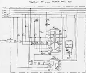
One thing to highlight here is that I confirmed that what I have been calling 0V#3 (that is equivalent to 0V(D) in the M-500 schematics) is indeed completely isolated
to the 6V rail. 0V#3
will not form a complete circuit for the 48V, 35V or 15V rails, and neither will 0V#'s 1 & 2 (equivalent to 0V(C) in the M-500 schematics) form a complete circuit for the 6V rail. So I actually studied my own schematic last night to see first if there was something illogical with the flow of things at the present (i.e. +/- rails trying to resolve to an incorrect 0V rail), and I didn't see anything obvious, though I did keep nodding off at the time...
So that's good in a way and not so good in another...It sorta means my assumptions were right, that the actual circuitry matches what I hooked up to each terminal power-wise. What is not so good is that it is definitely not working and therefore more investigating is required.
So it is high-time to take a close look at Ethan's post and see if I can figure this sucker out.
I must say, however, that I continue to be completely baffled as to how 0V#3 is isolated from #'s 1 & 2 when they are all connected to the same trace in the PSU...??? 
Furthermore, since I'm understanding things better, I think I need to do away with the whole idea of labeling the 0V rails in the M-___ as #'s 1, 2 & 3...I'll stick with 0V(C) and 0V(D)...I originally went with the former not knowing whether or not they were 3 distinct and isolated 0V rails, but it looks as though the M-___ thirsts for only 2 of them, just like the M-500 mixers so we'll stick with Tascam's nomenclature of 0V(C) and 0V(D).
 ) should it be shorted.
 :rolleyes:")

")