Tascam M520 Story...

M500 shorting pins?

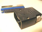
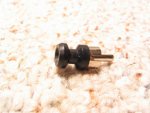
Look at the picture below...

It is a Tascam shorting pin that comes with the M500 mixers (others as well I assume). This goes somewhere on the mixer. This is not the bridge type shorting pins that go in the SEND/RCV jacks...

Anybody know how many the mixer should have? I think they are used in the phono input jacks on channels 3 and 4, and/or in the INST input RCA jacks on channels 1 and 2, or both. The manual is not clear.
 

Attachments

  • IMG_7241_3_1.JPG
    IMG_7241_3_1.JPG
    47.8 KB · Views: 280
Hmm...

So here's what I did:

I plugged the power supply in. No bad noises, smells or sights (i.e. SMOKE :eek:). Turned it on, same thing. So far so good. Let it sit powered up for a few minutes occasionally sniffing. No prob. Happy box. Got out my multimeter. The outlets in the shop are three-prong so I test to see if I get voltage accross the hot side and the ground of the receptacle...118VAC...okay...its grounded. I connect one side of my multimeter to the "GND" lug on the back of the PS520, Set the meter to volts AC (it is auto-ranging), made sure the probes were in the right sockets on the meter, and then stuck the other probe in the ground socket of the wall receptacle. 70VAC. Wha...??? :eek::confused: 
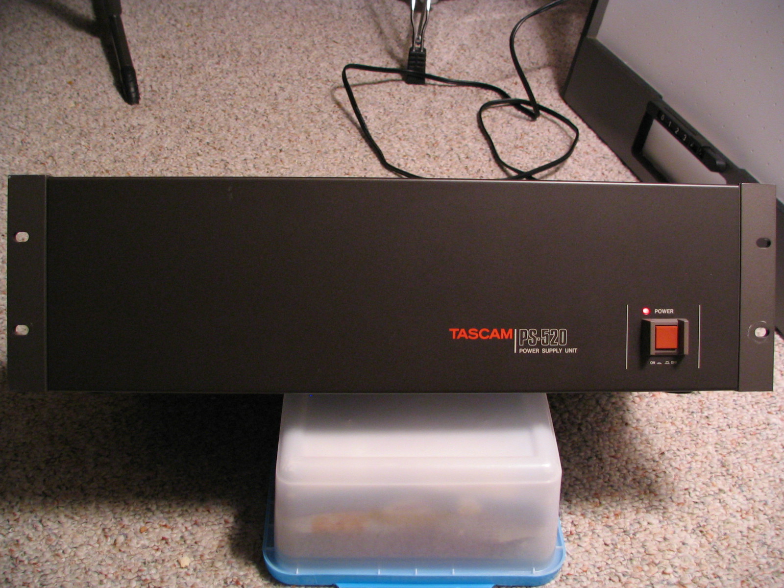
I clamp the probe that is on the PSU to a rack ear, stick the other back in the ground socket, same thing...70VAC. Its late, I'm not trusting my meter, I slap the case with a finger. Nothing. I'm now feeling like Ben Stiller and Owen Wilson in Zoolander when they are trying to find the "files" in the iMac and they are beating on it, shaking it upside-down and making primal noises...I realize I'm not going to feel 70 volts of fun unless I cram my finger in the ground socket and touch the case...I look at the case, the wall, back to the case...nnnnnnnn...nnnaw. Its late...better judgement gone...all gone.

WHAT DOES THIS MEAN??? :confused::confused::mad::(

Beck...I should have read your post first...I bet it will work right tomorrow.

So what do I do?

Daniel, how do you know its from '88? Does it have to do with the "884" at the end of the s/n? That's pretty late for an M500-series console isn't it? How long did production run on those?

Dave...Dave...so are ya confirming the shorting pins are for channels 3 and 4 or are ya putting in yer vote? :rolleyes::D
 

Attachments

  • zoolander.larger_0.jpg
    zoolander.larger_0.jpg
    10.5 KB · Views: 399
Shocking discovery...

So I plugged the PS520 into my Monster power center. Its the 2500 model. Not an isolated power center, but regulated and filtered with ground-fault and voltage indicators etc. etc.

Same thing...when I measure AC volts across the PS520 chassis and the ground socket (or any grounded surface) I get about 70VAC. So I put the DMM down, placed me left hand on the chassis of my Furman power distributor (which is grounded), and tapped my right hand on the chassis of the PS520 and...nothing. I double-checked the two surfaces with the DMM and sure enough it reads 70VAC. Tried it again with my hands,..nothing.

I checked amperage and there is no current.

WHAT IS GOING ON?? ???
 
Antenna

I see from the photo that this PS has a 2 wire line cord with a ground lug for connection to a common audio ground.

In that case I would say that the 70 volts is the leakage current. The unit is expected to be tied to a single common ground through the lug but not through a power cord so as to prevent ground loop induced hum.

What happens if you reverse the line cord (pull it out, rotate it 90 degrees then plug it in again?)

In any case I would run a ground wire to the PS lug.

As for using your hand to test. the last time I did that (quite by accident) it left a trail of charcoaled burnt skin across the back of my left hand... Smelled bad too.

A 120 volt lamp works better than your hand....

Just some thoughts. I should not that I am not an electrician nor do I play one on TV.
 
I would say that the 70 volts is the leakage current

so does that mean the PS is malfunctioning? And why can I measure voltage using the DMM but cannot feel anything with my hand??

To what do I connect the ground lug then? Is it supposed to be connected to a ground stake with a distribution lug block?

Yes.......

Dave, thanks! :D
 
Daniel, how do you know its from '88? Does it have to do with the "884" at the end of the s/n? That's pretty late for an M500-series console isn't it? How long did production run on those?

Yes, the 884 means it was made in the 4th quarter of 1988, which is indeed quite late for the 500 series. I'm not sure when the end of production occurred but I betcha it was soon after that.

----
 
Should e OK

so does that mean the PS is malfunctioning? And why can I measure voltage using the DMM but cannot feel anything with my hand??

To what do I connect the ground lug then? Is it supposed to be connected to a ground stake with a distribution lug block?


Dave, thanks! :D

Leakage voltage is a voltage measured through a high resistance path. High resistance equals low current equals no power.

THe ground on the back of the PS should connect to your single point analog studio ground:cool: (if you have one)

Somewhere you do have a grounding stake but you don't want a second.

-Ethan
 
Ethan,

So...I know where the grounding stake is...I don't have a single-point analog studio ground...should I have one and run a ground line to the studio from that stake?

Sorry if I'm just not getting it with the leakage voltage...is leakage voltage bad? I obviously have it, but does it mean something is wrong with my PS520??

Daniel...that's cool with the s/n. Thanks!
 
Nothing wrong

Nothing wrong - you are still alive :D Leakage currents are through dust, dirt, and other contaminants and or induced currents. because of the high resistance you do not get any current which would be bad. (I = E/R) Sounds like you have a good meter in that it has a high input impedence and does not load up the DUT much. A bad meter with a low input impedence would pull the measured voltage closer to ground.

I think that your PS is fine.

All this is from memory from school many moons ago. (leakage current ant that)

You do not need a single point ground. The advantage of a single point audio ground is to combat hum caused by ground loops. The idea was to tie all the protective grounds together at one point and to tie all the audio grounds (in your PS case the ground bolt on the back by the power cord) together at one point, and to tie that to the protective ground at one point.

You are powering your equipment from (most likely) 1 breaker box which is where all your protective grounds are tied together (neutral too). This gets rid of 99% of the problems.

In my case I power all my audio from 1 UPS. This forms the tie point for my protective grounds. Everything plugs into my mixer which forms the tie point for the audio grounds.

Hope this is not more confusing....

-E

PS back to your PS. Build that cable out of individual wires if you need to and run them through some (big) heat shrink.... Are you missing cable or connectors or both? Time to fire that thing up!
 
One down, one to go...

Still haven't heard from Tascam on the connector for the other end of the umbilical, but I got one end and the other is officially back-ordered. I'm hoping that means it is not discontinued. I will be contact Tascam tomorrow as I had intended to do earlier.
 

Attachments

  • IMG_7386_1_1.JPG
    IMG_7386_1_1.JPG
    44.9 KB · Views: 293
For Ethan...

Nothing wrong

--------------------------------------------------------------------------------

Nothing wrong - you are still alive Leakage currents are through dust, dirt, and other contaminants and or induced currents. because of the high resistance you do not get any current which would be bad. (I = E/R) Sounds like you have a good meter in that it has a high input impedence and does not load up the DUT much. A bad meter with a low input impedence would pull the measured voltage closer to ground.

I think that your PS is fine.

All this is from memory from school many moons ago. (leakage current ant that)

You do not need a single point ground. The advantage of a single point audio ground is to combat hum caused by ground loops. The idea was to tie all the protective grounds together at one point and to tie all the audio grounds (in your PS case the ground bolt on the back by the power cord) together at one point, and to tie that to the protective ground at one point.

You are powering your equipment from (most likely) 1 breaker box which is where all your protective grounds are tied together (neutral too). This gets rid of 99% of the problems.

In my case I power all my audio from 1 UPS. This forms the tie point for my protective grounds. Everything plugs into my mixer which forms the tie point for the audio grounds.

Hope this is not more confusing....

-E

PS back to your PS. Build that cable out of individual wires if you need to and run them through some (big) heat shrink.... Are you missing cable or connectors or both? Time to fire that thing up!

Ethan, thank you.

That helps.

I haven't had any trouble wth hum so far, but if I do I'll be referring back to your post. Yes my "studio" is powered from one breaker box which ties to one ground stake.

Hadn't thought about building a cable from individual wires...not a bad idea. I may very well go that route. ;)

BTW, I'm using a Fluke 85 DMM. Got it off of eBay. Pretty good shape. Purchased it specifically for its specs and bandwidth. Happy with it so far.
 
Did some power supply testing just now...have questions.

So I did some no-load testing of the PS-520 just now. Not sure if I did this right...I connected one lead of the DMM to the chassis ground-lug on the back of the PS-520, and probed each socket on the multi-pin connector with the other lead. Please comment. Results below:

-15V (Pins 14, 15) A-OK...both steady at -15.21VDC
0V (C) (Pins 8, 9) A-OK...both steady at 0VDC
+15V (Pins 1, 2) A-OK...both steady at 15.20~15.21VDC
GND (Pins 12, 13, chassis) A-OK...solid continuity with the chassis ground lug.
+48V (Pin 16) A-OK...steady at 47.4VDC
0V (D) (Pins 10, 11) A-OK...both steady at 0VDC...they take a few seconds to get there though.
+6V (Pins 3, 4) Hmm...:( 0.001VDC
11V AC (Pin 17) Hmm...:( 4.71~4.72VAC
11V AC (Pin 18) Hmm...:( 5.42~5.44VAC
-18V (Pins 19, 20) A-OK...both steady at -17.88VDC
GND (same as above) A-OK as above
+18V (Pins 6, 7) A-OK?...both steady at 18.32VDC

Comments?

Again, these were all no-load tests to chassis ground using the appropriate settings on the DMM.

I physically manipulated the fuses on the mainboard in case there was any oxidation.

Here is a pic of the face after cleaning it up...
PS-520%20Face.JPG


And here is a pic of the guts. Pretty clean in there...
PS-520%20Internal.JPG


Also received the additional input block and master section parts units. I'm glad about this because I need a couple bits from the master section. Nice insurance to have the spares. Lots of them though. If any of you need pots and such, let me know. I may be able to help. :)

Next up: If I can get the +6VDC and 11VAC sections figured out I'll likely direct-connect the PS-520 to the M520 for a load test...that will be scary for me...:eek:
 
11 Vac

The 11 VAC is measured from pin to pin and not to ground. (it is isolated from the ground)

+6 --- Do you have a power LED? It is also driven from the + 6 supply. Measure at the collector of Q010 to verify that there is 6V.

-Ethan
 
The 11 VAC is measured from pin to pin and not to ground. (it is isolated from the ground)

DOH! Right! Okay...My son and I just measured the 11VAC pins at 10.81~10.95VAC. Good?

Okay...my son and I finally found Q010 :), but couldn't find an exposed trace or wire without having to pull the main PCB...the three wires go to the heatsink, but we didn't pull apart the harness to see which component...we didn't want to do with lotsa live voltage in there. :) What is the collector side? The input side?

But what we DID find was 6.38VDC between pins 3 or 4, and pins 10 or 11, the 0VDC (D) circuits...so does that make sense? Is it alive? I don't really understand the 0VDC control voltages...it is a new concept to me and I really don't understand the (C) and (D) suffixes.

Thanks so much for your help, Ethan. :D
 
Ethan, I can't thank you enough for the vote of confidence on my power supply.

I'm putting the faders back in the mixer but leaving all the dress panels and knobs and caps off...that will make it easier to get the deoxit I'm sure I'll be using to where it needs to go. :)

Once all the faders are back in then it will be time to direct connect the M520 and its matching PS-520 together and push that big orange button :eek:!

It'll be a couple days tho'...I'm camping. :D

BTW I talked to the parts specialist at Tascam again today and no word back from Japan yet on the availability of the backordered umbilical socket connector. She said she'd put a second request out for an ETA on the part and, again, that will offer the chance for an expedited answer on whether or not the part is still available. It is still active in their system, but she confirmed that nobody's ordered one for a long time and it my have been discontinued in the meantime. Here's hopin' it hasn't!
 
I'm on the hunt....

Check out what I found in the boneyard at my local favorite elctronics shop... :eek: I spotted it in a basket of miscellaneous stuff...couldn't believe my eyes...its a hood for the power umbilical.

The hood is a little dirty but there is absolutely no corrosion. Unfortunately there were no 20-pin female sockets, just 60-pin male sockets (I picked up one to practice soldering on) and just one hood...I picked up the pair for $1...If I can get the 20-pin female socket side and hood from Tascam (still waiting for word) I'll do so and keep the hood I found today as a spare. If I can't get the socket end, then I'll keep looking for the socket to complete the hood I found. I've found that the connectors and hoods are manufactured by HRS, a.k.a. Hirose. They closely (at least for what I can see) match the 1300-series which were designed for telco equipment.
 

Attachments

  • IMG_7416_2_4_1.JPG
    IMG_7416_2_4_1.JPG
    27 KB · Views: 263
A new obsessive cleaning trick...

If yer not anal-retentive with cleaning up gear, walk on...

I stumbled on this last night trying to clean up the faders for the M520...maybe its a bad idea as it pulls some of the fader grease out, but I was using the rubber pick end of an old toothbrush to pull a piece of fuzz out of the end of a fader gasket...a big puff of fuzz ended up coming out, so I ran the pick under both sides of the gasket and pulled out several gobs of linty fuzz. The picture below shows what I pulled out of one fader after only running it down part of one side of the gasket.
 

Attachments

  • IMG_7417_1_4_1.JPG
    IMG_7417_1_4_1.JPG
    25.2 KB · Views: 264
Back
Top