Tascam 58-OB Story...

  • Thread starter Thread starter sweetbeats
  • Start date Start date
Cory, sorry to not have followed the thread too close but what exactly happened to cause the electronics failure of the machine? I apologize in advance if this was answered before.:o
 
Cory, sorry to not have followed the thread too close but what exactly happened to cause the electronics failure of the machine? I apologize in advance if this was answered before.:o
He used an extender card on one of the channels. It was off by one pin, which IIRC shorted the 25v line to ground, blowing up the power supply and probably destroying that channel. By the sound of it the control logic is all still intact, so with the possible exception of the channel card, it seems to be all repairable.
 
He used an extender card on one of the channels. It was off by one pin, which IIRC shorted the 25v line to ground, blowing up the power supply and probably destroying that channel. By the sound of it the control logic is all still intact, so with the possible exception of the channel card, it seems to be all repairable.

By one pin, you mean it was missing or bent or..? Thanks jp!:)

--
 
Daniel, the first picture in post #273 tells it all. :(

Thanks for covering me jpmorris. :p

Carelessness...nothing less...and it didn't help that I wasn't wearing my glasses which was also careless.

One thing for sure is that it will be a reminder forevermore to stop and think and look one more time. Get in a hurry and stuff happens.

I'll know more this weekend.

The upside is that I'm learning a bunch. There are always two sides, but I have to say I'd be stuck without everybody's help. Its the warm fuzzy of this forum. I can clearly imagine making a careless mistake like I did and posting up on an unnamed forum and either getting no reponse or a "what a dumba**" reply. Really sad. But the community atmosphere on this forum is great IMO. Thanks everybody!

I'm prepared for the worst on this. It would be my pennance. :o So far so good though, and as Ethan mentioned a few posts back, the VU meter and associated peak LED may be damaged, but I have spares of those, and amp card #8...I will be very shocked if this is intact so I'm anticipating work there as well. Beyond that I'll find out as I go. ;)

Stay tuned...:)
 
One of the reasons I have made my home here is the same as you mentioned Sweetbeats... the attitude at most other forums is pretty bad. I get the impression that the average age here is a bit older than most forums as well... plus anyone willing to take the time to go back and fiddle with the old analog equipment is bound to have more patience than is ordinary.

AK
 
Yup...wisdom.

Good example for us "young bucks", and the young at heart. :p

I can only hope to return the same or more in kind or pay it forward. It keeps it going. ;)

Had my very good bass player/guitarist/singer friend over last night. Haven't seen him in awhile and we talked quite a bit about the unique elements of analog tape systems, did some listening to music and did some tracking (albeit direct to disk with the 58 out of commission :o). We talked at length about the fast-food culture we have progressively become over the decades in many areas of life and how the analog world pushes back on that trend...as well as demanding more of the artist when utilized in a traditional way. I'm really excited to be a part of that...and I could care less if it is popular or practical, though it isn't the opposite of either of those...my point is that its not mainstream, and that only adds to my respect for the medium. I'd have the same level of interest if it was mainstream tho'. I can remember seeing the TSR-8's in the internet retailer catalogs not so many years ago alongside the 238's...I knew it was a dying market sector, and I remember being somewhat distressed at that because I knew the day was coming that I'd want to get back into analog recording and I didn't know where that sector would be when I had the means and locale to do it. Well, that sector is alive and well! ;)
 
And considering I paid $500.00 for my TSR-8, not $5000.00 is a bit of a bonus nowadays for those of us "in the know"... :)
 
More questions when anybody has time...

*note* these questions refer to the amp card schematic; when I offset the card, pin 1 was plugged into nothing, pin2 into socket 1, pin 3 into socket 2, etc.):

  • What kind of diode is D22 (straight above the socket for pin 9)? I'm unfamiliar with that symbol.
  • Might my heads have been damaged? I'm looking at what went where, and for instance pin 4 (-15V) went into the socket for pin 3 (repro head -)...15 went into 14 (sync head - into +), and 25 into 24 (erase head + into -)...
  • Is C8 a filter cap? I'm just trying to get familiar with connecting functional terms that I've learned with recognizing them on a schematic. C8 goes between sockets 4 and 6.
  • What would likely happen to C28 as a result of getting a stright shot of 24V?
 
Power Supply Fault

Well, it seems that one of the 15V rails on the PS is bad...not sure why yet. Need to study the schematics and start tracing backwards. It is the 15V supply found on connection #27 on the Power Supply PCB. No surprise it heads for the Mother PCB and on to the amp cards, as well as the Control PCB...hm...maybe why the reel motors weren't working???

Had quite the time getting the PS out...all the wires are solder mounted...can't get to the screws until you pull the capstan motor so I did that, and then you can't get the PS PCB out of the deck unless you remove the function PCB and maneuver it through the frame...I've got so many screws on the table now I think I need to start labeling them, and review which connections I've disconnected and maybe shoot a video for myself as to what goes where. I know I could figure it out from the schematics, but that can be difficult when wires get bundled and head off somewhere in an annoying way...

Here's a shot of the back of the 58 after tearing it further apart this eve...
rear%20view%202008%2008%2009.JPG


And here's a closeup of the PS...
Power%20Supply.JPG
 
Last edited:
Soldering Frustration...

Tried to solder the resistor back into R5 on the Mother PCB.

I can't get the solder to weld to the PCB! :mad:

Well, maybe it is welded in one spot, but the other joint is not welding with the PCB. I don't want to damage the PCB...

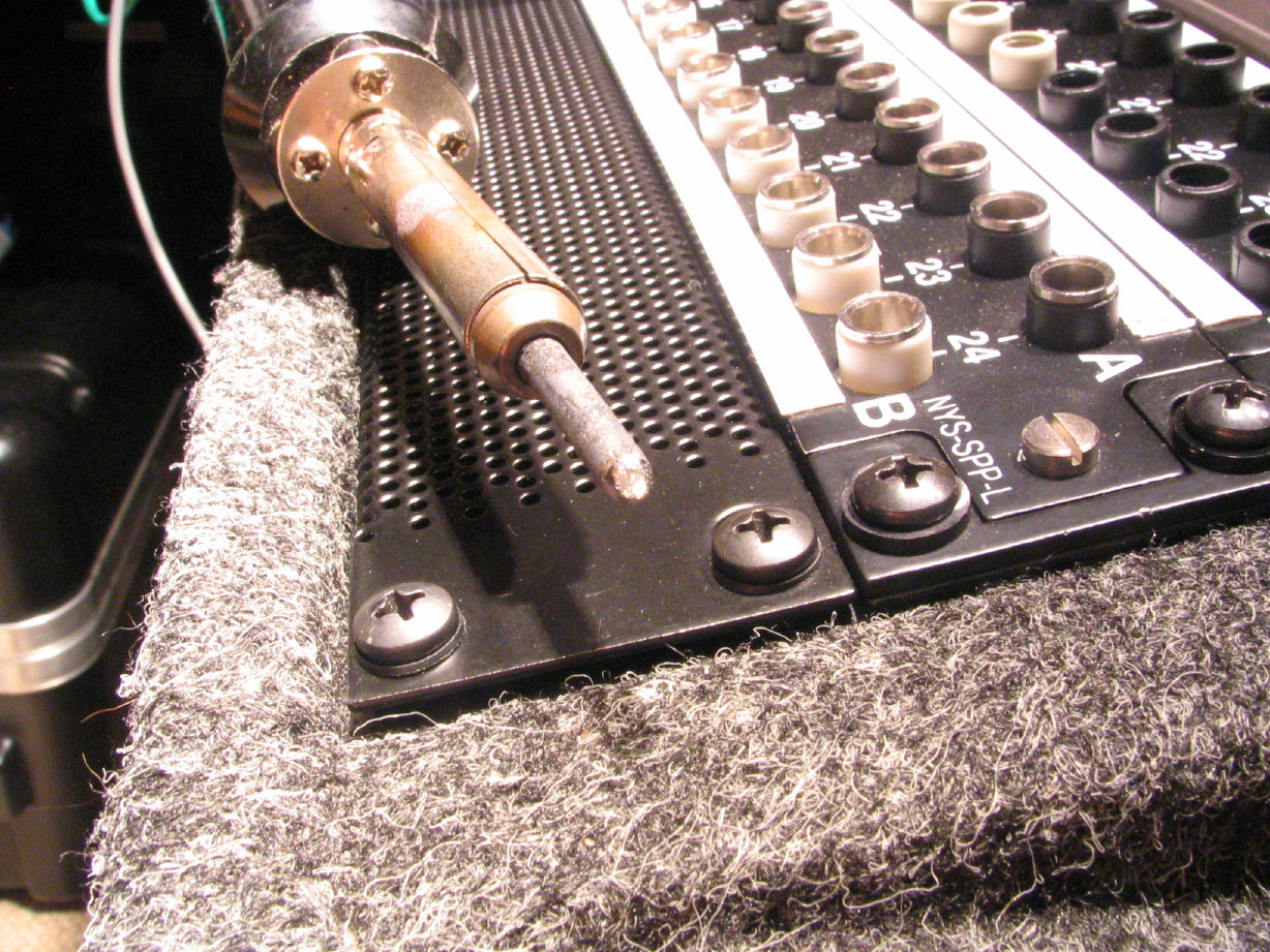
Maybe it has something to do with my iron:
soldering%20iron.JPG


Older basic Radio Shack iron...tip is ugly...I have a new iron on the way.

Could that be the problem?

Here is a closeup of the iron tip as well as a closup of the joints on the PCB...nothing stuffed in that pic...I pulled out the one I was putting in because the joints looked so bad.
 

Attachments

  • iron tip closeup_1_1_1.webp
    iron tip closeup_1_1_1.webp
    21.6 KB · Views: 103
  • ugly solder job_1_2_1.webp
    ugly solder job_1_2_1.webp
    23.4 KB · Views: 108
A new tip on that iron might help.... or possibly a better iron. I'm sure tehre are many people that can give you better soldering tips - I can operate an iron but I wouldn't call myself expert by ANY means.


AK
 
Hm...I'm in over my head.

Tried doing some diagnosing on the PS tonight to see if I could find a failed component...

Referring to the Power Supply Schematic, tracing back from lead #27 (the 15V rail that is dead), the trace comes to IC "U2", and cap C18. Cap C16 is also in that neighborhood cpnnected to U2. I thought I'd start just checking for basic continuity in components knowing that I'd have to pull one leg of the caps to really know what's happening with them. Not sure what I touched to what, but as I was moving my DMM probe into position to measure across the leads for C18 I got a spark...not a little spark, not a big one either, but the kind tha gives a little pop and a very visible spark and leaves a scorch mark on the tip of the DMM probe. The deck has been unplugged for days...do large caps store up energy that long?

Anyway, it shook me up a bit. Studied the schematic for awhile, learned what U2 is but still not sure what it does. Didn't feel confident to desolder one leg of C18 or C16 for that matter with my old soldering iron, especially after the spark.

Can anybody look at the schematic and offer any advice? I suppose I might check the rectifier D10...maybe something cooked in that?
 
One step at a time grasshopper...

Okay...so "U2" is a +15V regulator...that makes sense. It has three terminals, IN, GND, and OUT. I should be able to test it by checking for continuity between IN and OUT right?

I guess the other thing I could do is, since the IN side taps off a +24V rail, I could power the deck up and see if I have 24V at the IN terminal, and double check to see if there is voltage at the OUT terminal...that's what I'll do.

I need to keep in mind that this needs to be taken one step at a time. I need to analyze and think carefully about what the next logical step is, and then consider the results of executing that step. I wasn't really sure what to do next last night so I just started probing around. After looking at the schematics again today and researching the NJM7815A component that is U2, it becomes clear that that is the next upstream link in the circuit from terminal 27 on the PS PCB, the terminal where there is no +15V and there should be...if voltage is not getting through that regulator from the +24V rail, then it needs to be replaced. Simple. One step at a time. Patience.

One thing I don't understand and would really like to understand is what C16 and C18 do...do they provide a smoothing function?
 
Keep after it man.... wish I could be of some help here but I am still reviewing my remedial electronics books in hopes of remembering enough to tackle the burned out PR99 I have.


AK
 
I think "U2" is toast...

The voltage regulator, not the band...you all probably knew that, but I want to be perfectly clear. I like the band quite a lot...October is one of my favorite records of all time...played it so many times it is probably why my Sony linear tracking turntable stopped working...aaaanyway...

So I Did what I stated I was going to do...I measured the input voltage of U2, and checked the output voltage. 32V going in (unregulated 24V supply), and....nothing coming out. Just be sure I compared to U3, a 5V regulator. Voltage goes in, and voltage comes out. Even when powered down I get some continuity between the input and output of U3, but not U2. I think its toast. It is an NJM7815A. I've only briefly checked DigiKey, and the search turns up nothing. Hoping this is not a difficult IC to find. I did check the schematics for my parts 48 and it has one in the PS, but I hate to put a used one in just in case some idget like me did something to that 48...:D New would be preferred. I'll Google it and check Mouser I suppose...or???
 
Okay...I know now why I can't find the NJM7815A regulators...it is discontinued, but there are suitable replacements...Mouser has a great technical live internet chat service...had a dialogue with a rep and they suggested the NJM7815FA...the FA just means "fully-insulated", which does not effect the performance characteristics of the component.

So now I need to decide if I'm going to purchase any other components, like caps for recapping the power supply and such...The caps look really good on the supply now, but I know looks are deceiving...Hm...:confused:
 
Back
Top