Tascam 58-OB Story...

  • Thread starter Thread starter sweetbeats
  • Start date Start date
Moving Forward

I have graciously received the information needed to move forward and purchase caps. If anybody else is ever interested in recapping their 58, here is a Tascam 58-OB capacitor list...it is in MS Excel format. I should also make it clear that this list ONLY deals with the electrolytics. Basically its got a tab for each PCB that has 1 or more capacitors, and on each tab is a chart with info about the capacitor(s). Then there is a summary tab that collates all the individual PCB tabs so you can get a grand total of each type of capacitor found on the 58-OB. You can look at just an individual tab if you want to know what caps are found on that PCB, or you can look at the summary chart and know how many of each type of cap if you are doing the whole deck, and then there's a color key on the summary chart so you can chase down which PCB's feature which caps if needed.
 
Sounds like you are making some headway. I am STILL unable to make time to get after that PR99 *sigh*. Doesn't look like I'll be doing much recording any time soon either, just too much business and family business gettign in the way right now.


AK
 
Enough burning flesh already

AK...just do what I do...skip the sleeping part...

Started practicing for recapping tonight on a spare amp card I got from Talldog...those things are definitely the most dense project I've experienced...it was a pain to pull the caps off of it because the holes in the PCB for the device tails are so small its hard to get the solder sucked out, and then its just a fight to get the component off withjout damaging the solder pads/traces, although these seem pretty robust...in fact, I noticed that the PCB itself is totally different construction than the cards that came with my 58...The bias amp on this card was marked "Bad" so I pulled the cover offa that, and decided to pull the covers off of the relays. put my left ring finger right on the shaft of the iron twice...duh...stinks...and also jabbed the tip into my thumb. Not my proudest evening.

Anyway, eventually I got all the caps off...but the relays look totally unfamiliar to me. They do not look mechanical...can anybody tell me if they were an upgrade or something? They are the two orange thingies in the picture...
 

Attachments

  • untitled1.webp
    untitled1.webp
    48 KB · Views: 101
Make sure you use the right solder for human flesh........


:D


Been there, done that. I don't recognize those relays are there any numbers
on them at all?


AK
 
The relays...

The relays have printed on them:

MR62-24S
NEC
JAPAN A8904S
 
Looks like a DP/DT relay, should still be able to find NEC replacements for those.


AK
 
Oh sorry for not being clear, AK...I know what they do, I'm just used to seeing the Omron mechanical relays and these look so different...
 
Those are the standard issue Original relays. I'm using Omron G5V-2-H1-DC24 for my replacements. Having brought 16 cards back to life (not the relays fault) abd having replaced the relays I can say that they work. And at mouser that are something like $2 each.

As for that bad bias amp... just replace the transistors and it should be good to go.

Ethan
 
Oh wow...huh!

All the other channel cards I have have the Omron relays with the clear cover on them.

Thanks for the reference on the Omron p/n you used with success.

I recall you commenting somewhere about the bias amp repair not being that big a deal...I think my problem at this point is that I can't get the whole module free of the amp card PCB to get to the solder joints for the transistors... :mad:

I've sucked all the solder my spring-loaded solder vacuum is going to get, and the holes in the PCB are so small I can't really get the tails free of the solder...suggestions/questions about this anybody...I think I need some advisement and I'm open to any clarification needed about how I'm doing it now...

Yes, getting it off the board is the hard part.

Suck away till you ger as much solder as you can. Then gently pry one side that see if any of the leads move. Those that do you need not worry about. Look for leads that have very little solder and see if wiggling them with a pair of needle nose pliers will break the lead free. then go back to the GENTLE prying and as you pry touch one of the leads with your iron. Quickly move on to the next lead. Move the prying to a new corner/sie and do those. Take your time and work it free little by little.

I've seen those clear topped relays on some of the cards here. Who knows the history.....
 
Thanks for the tips, Ethan.

I was wondering if there was something I was missing, but, no, it is just a careful and tedious process..."Patience, Grasshopper..." :D:rolleyes::o:p
 
I'm getting ready to recap the PSU and...

I'm trolling for any opinions on my replacement cap selections. Please check out post #66 here and lemme have it! :eek::rolleyes::D
 
Today, UPS delivered...

My 58 parts deck. :)

Special kudos to forum member PaulWarp...he gave me a VERY good deal on it...shipping only, and with the current exchange from Canada to the US the shipping wasn't actually too bad. Well worth it. :D:D:D

The parts deck is the victim of a prior shipping incident. If only PaulWarp had been the packer the first time. :)

I remember seeing it on eBay when PaulWarp ended up being the buyer...it was pretty sad looking. Skin was all twisted up. Those badly messed up parts got tossed, but that really only amounts to the side panels, top panel and upper back panel. Lots of other scratched nicked parts, reel adapters are TOAST (and even one reel table is gone but the hub is there :eek:) but...everything else is there. I haven't plugged it in yet to see what functions. I'll take a closer inspection in the next day or two, but at first glance the heads have minimal even wear, everything else in the tape path looks nice...its actually fairly clean. If it is what it looks like I've got good spares to keep my 58 going for quite awhile, and parts to swap out to expdite getting it going again after my tragic and careless mishap with the misinstallation of the channel card some time back.

I'll get pictures up in the next few days.

I have 5 decks now...Dave...WATCH OUT!!! :D:D:D
 
I have 5 decks now...

This is pretty smart though, Cory, 'cause you have several of the same model, which is always a good move, parts wise, to keep your decks going for a long, long time.... You are definitely a thinking man's collector. ;)

--
 
Thinking man's collector...I'll remember that the next time I'm asked just how many reel to reel decks I need...:D:D:D

Yeah...that's the way I see it...the 48 and its parts deck, and the 58 and its parts deck, and then the rogue BR-20T. Seriously, if I ever see a BR-20 up for parts or repair I'll probably try to snatch it.

The 58 parts deck may look like a non-functioning piece of obsolete gear...worthless...but to me its a goldmine. Having spare PCB's of everything...spare capstan motor, counter roller, tension sensors, all the tape path hardware...HEADS, headblock...two more reel motors :rolleyes::eek::D, a full set of 8 channel cards...boy howdy. Did I say kudos to PaulWarp???

I'm starting to think that I may pair the 58 with the M-___...they make a nice pair because the 58 was one of the last decks to have a hint of that Tascam orange on it, just like the M-___ fader trim strip, and the M-___ is setup for an 8-track deck...wouldn't they look nice together?

Need to find another CS-607...
 
Meet the parts 58...

Here is PaulWarp's packing job...he put it in an Otari box with the foam blocking and put the deck in a plastic bag. Pretty nice packing, especially for a deck that has already been toasted.

01.JPG


02.JPG


Loose bits were put in a ziplock...the flip-up portion of the head cover has literally been torn off...oh there's the other reel table...

03.JPG


Here is a shot of the back...again, the side panels, top panel and upper back panel are gone...too damaged to be worth anything except a testament to evil shipping and handling. You can see the upper sections of the frame sides are buckled out...this deck took a serious hit to the top. The RCA jack panel has a nice dent in it too...notice the control PCB (the one dead center facing out in the upper section) looks kinda funny?

04.JPG


This is what is really funny (not ha ha funny) with the Control PCB...

05.JPG


Moving down now, one of the hinges for the upper connector panel is missing parts so it hangs funny, but that's not as bad as the bow in the top edge of the panel as seen here...

06.JPG


Here's a closer look inside. Things look pretty good in there. Just normal dustiness. Overall this deck is cleaner than my parts 48. It really does appear to be a reasonably cared for low-hours deck. Sad.

07.JPG


Now we move toward the front of the deck. Here is the top corner of the right sash (the main rails to which pretty much everything attach...) More evidence of that hit to the top. Notice the top of the sash is actually tweaked...pulled away from the deck. Those sashes are pretty heavy-duty.

08.JPG


The upper dress panel looks nice though, and the reel motor heatsinks and the transformer look fine...

09.JPG


Upper dress panel removed...everything looks fine in there, and I'm pleased that the solenoid cushions aren't gooey.

10.JPG


The bottom panel, save for some scratches, looks great which is nice because the bottom panel on my good 58 is tweakered in some way making it a pain to slide the VU meter panel out to access the cards.

11.JPG


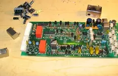
And speaking of cards, yup, they're all there and they look unharmed. ;) Can't get the VU meter panel all the way out tho'...the right slider hinge is hung up on something. Notice the card cage is actually separated from the main frame...not sure if screws got removed or what...

12.JPG


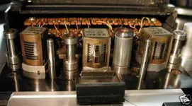
Tach roller and left guide...need cleanup of course (as does the whole tape path) but otherwise it looks to me as though the whole face of the deck was spared.

13.JPG


Erase head, sync and repro heads...same thing. Dirty but in good shape. Zenith might be a shade off on the sync head? Looks like some shedding tape was run on this deck.

14.JPG


15.JPG


16.JPG


Last but not least, the capstan shaft and pinch roller. Again, these actually look pretty nice.

17.JPG


So I must admit...after taking a good look over the deck and looking at the fuses I decided to power it up...Have I learned nothing? :eek: Couldn't help myself. I know I didn't do any additional damage. :p

Here's the story on the current status of this deck...

  • One VU meter lamp dead
  • All lights on the arming panel work and I can hear relays clicking when switching monitor sources.
  • After the power up delay both reel motors start spinning and don't stop until it is powered off...tension arm position has no effect.
  • The capstan motor is not spinning.
  • The keyboard and counter display are dead, so no transport functions can be tested.
  • The brakes are on all the time.

So, I know the reel motors are good, hoping the capstan motor is good too. Clearly the logic is messed up and I think I can blame the busted control PCB for that. :) At some point I'll pull the plugs on everything and test the voltages of the power supply just so I know what's what, and then put it on the shelf for future cannibalization. Sad, but at least this deck still has prupose and value in keeping another going.

It may sound strange, but for those of you that have been keeping up on my Tascam 48-OB Story you'll know that I was really taken with the vast differences in engineering logic between the 58 and the 48; the 48 being worlds ahead of the 58 in how it was put together and designed, but having my hands on a 58 again I feel a sort of kinship connection with the 58. Maybe its because I've spent so much time on my 58 trying to get it running "just right" :rolleyes: and I'm familiar with it...I don't know, but I most certainly haven't cast off my affection for the 58 in lieu of the 48. The 48 will be operating in the studio before my 58 for sure, and the 48 sure is neat how it was put together and how much easier it is to setup and maintain, but there is something really cool about the 58.
 
Man, Cory, what an awesome and kinda sad pictorial of a once nice, lower use 58.:( It does indeed take an enormous amount of stress to damage a 50 series recorder in such a fashion. It happens more than stats would indicate. Pretty sad. On a lighter note, it seems that the 'tank' like chassis and built of the 58 served the role to actually spare the audio cards and the like. ;) Still, pretty sad.. I will, however, put up the link to your photos on the packing 101 thread.
 
80-8 heritage in the 58

I know that Teac, in response to market demand, essentially split the 80-8 into two models...one at a lower price-point geared toward the professional home-recordist (the 38), and one at a higher price-point with a more robust transport and other professional features like a full-function remote and the ability to synchronize (the 58).

I've always enjoyed the tape path on the 58 with the 3 guides and the scrape filter...thought those features were unique, among Teac's/Tascam's 1/2" 8-track decks, to the 58. Nope. All this time and I didn't realize that they pretty much dropped them into the 58 from the 80-8.

Pic of the 80-8 headblock...same 3 guides and scrape filter as the 58. :eek:
 

Attachments

  • 4e7f_12.webp
    4e7f_12.webp
    23 KB · Views: 455
Back
Top