F
You are using an out of date browser. It may not display this or other websites correctly.
You should upgrade or use an alternative browser.
You should upgrade or use an alternative browser.
F
frnkfrkl
Member
F
frnkfrkl
Member
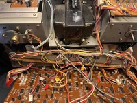
Yeah, if I don't want to unwrap those bundles, I think the transformer, fuse holder and board will come out as a package. There are some wires soldered to the control board as well so it'll be a balancing act unless I want to start desoldering those, too. And I don't, really. Not for one transistor. So. That's a tomorrow project. I looked at Mouser and Digikey but neither of them cross-reference to 2CS1645B. NOS, yes, in the States (I'm in France), $17.95 a pop plus shipping, plus customs....for a transistor. $0.76 AliExpress but who knows what reference or what I'd actually receive. This whole project has waited 30 years (transferring tapes to computer) so tomorrow I'll just see if I can get THAT whole mess out of there and just stare at it until I can find a transistor. No big rush...keep calm and carry on, as the Brits say.
sweetbeats
Reel deep thoughts...
I wasn’t saying looking on the Mouser or Digikey website for cross-reference. Get old-school and call them…or open a live chat.
Generally it’s possible to navigate PCB assemblies out around hard soldered wires…it’s not uncommon for the power supply to have to dismount the main transformer, power switch, fuse PCB…
Not sure what the shipping would be, but, no, never spend money like $17.95 on a small current TO-92 transistor…that’s why I commented about shopping diligently…quick eBay search bring up these options:
https://ebay.us/m/egZpmU
https://ebay.us/m/BUTrU3
Yes, who knows what the shipping would be for the first one, and it is certainly a reasonable concern to question the authenticity of the component in the second one, but counterfeit parts are much more a concern or common with integrated circuits. I’d be comfortable purchasing either of the above.
sweetbeats
Reel deep thoughts...
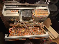
And yeah okay I think if it was me I’d dismount the main power transformer, fuse PCB, and that sensor PCB mounted to the back of the takeup reel motor…take lots of pics, put hardware into different labeled baggies…those steps might help you make some gains with extracting the power supply PCB.
F
frnkfrkl
Member
And the back board (control). It's on a bracket with just two screws so it'll come out with the rest. I ordered the transistor(s) from the first link. I bought 5 because, well, ya never know. Not too painful, shipping, etc.
One further question: should I be looking at D805, rectifier diode and D806, switching diode? D805 should be fine because I'm seeing 6Vdc at pin 1. I've got a 4006 around here somewhere which, I imagine would be overkill. D806, I'm not so confident because it is inline with the transistor and the bridge rectifier and something caused the transistor to fail and blow the fuse. Old age, maybe but while I'm there...I could probably do a complete recap, as well and I probably won't though the caps would be more easily sourced. Hmmm....it's just, how far down this rabbit-hole do I want to go?
One further question: should I be looking at D805, rectifier diode and D806, switching diode? D805 should be fine because I'm seeing 6Vdc at pin 1. I've got a 4006 around here somewhere which, I imagine would be overkill. D806, I'm not so confident because it is inline with the transistor and the bridge rectifier and something caused the transistor to fail and blow the fuse. Old age, maybe but while I'm there...I could probably do a complete recap, as well and I probably won't though the caps would be more easily sourced. Hmmm....it's just, how far down this rabbit-hole do I want to go?
sweetbeats
Reel deep thoughts...
Personally I would not suspect or have concern with D805 and D806. I mean, you can test them, but this is a relatively low voltage low current circuit, and all those diodes do is ensure proper current flow at power up and power down in order for the transistor “on” state to be delayed at power up, and go “off” first at power down. We know, based on your tests, the transistor Q801 is bad. It may have simply failed from age, and went dead-short emitter to ground. Current if I understand the circuit correctly current is t supposed to pass to ground through Q801…the emitter is a reference to ground so the transistor knows when to go “on” depending on the voltage level at the base. But if it failed and current went to ground through Q801 when it failed, I think that would pop the fuse…and after failing Q801 might be open circuit to ground which is why it’s not blowing the fuse, but also not passing enough current to the collector to energize the muting relay coils. You could always test this and clip the emitter pin and jumper the base to the collector, turn it on and see if you have audio…beware you will likely get a power thump in the outputs at power up, so turn down the volume level of your monitoring system. I realize you’ve got it all pulled apart now and that can be scary trying to ensure nothing is touching anything it shouldn’t be touching. I’m sorry I didn’t think of this earlier, but it is something you could do to verify the rest of the circuit is working…verify the transistor is the culprit.
If you do this, again, make sure you allow adequate time for the large caps on the power supply PCB to drain before working on anything.
Regarding the rabbit hole, if it was me, I’d probably recap the power supply while you have it out. If you do this, at minimum, use 105C temp rated caps.
If you do this, again, make sure you allow adequate time for the large caps on the power supply PCB to drain before working on anything.
Regarding the rabbit hole, if it was me, I’d probably recap the power supply while you have it out. If you do this, at minimum, use 105C temp rated caps.
F
frnkfrkl
Member
I understand the chain of events and it makes sense to me.
As for the caps, man, I've spent so much time inside this beast...It sat dormant for about 25 years, too. I know caps can go bad from just sitting, but I've got no hum and no bulging tops on the caps or visible leaks. My only use for this machine is to get tapes transferred to my computer. Once that's done, I'm going to sell it and it can becomes somebody else's headache. I'd probably spend more time just writing down the cap values, measuring their sizes, sourcing them (Mouser, France has a vast array of choices) and ordering them than I would actually installing them.
I need to get maybe 72 hours more actual operating time out of this thing and then I'm done with it. If they can just hang on that much longer...if they don't, well, I'll just get the screwdriver back out.
sweetbeats
Reel deep thoughts...
I completely understand. I didn’t realize you were going to be passing the machine on after your project. You probably said that.
FWIW I very rarely see caps in the failure states you mentioned in period Teac equipment; bulging, leaking, etc. they used good quality caps for the day. That being said that doesn’t mean the caps haven’t fallen out of spec. The electrolyte dries up, and you can’t see that visibly. But if the power rails producing the correct voltage and there is minimal to no AC ripple, the benefit you would likely gain is maybe an audible drop in the noise floor, which may or may not be any benefit relative to the inherent tape noise…and there would also be the benefit of some functional insurance against future failure, which is of relatively little value to you in your situation. You would also be able to market the unit as having a recapped power supply, but that probably wouldn’t help you actually sell it, or command a higher selling price. So your plan makes sense I think. I’m just stating all this here for future readers as things to consider against their own situations and misconceptions about caps.
Keep us posted…curious to know if the transistor replacement gets you on the road.
F
frnkfrkl
Member
Yeah, that's where I'm at. I've already transferred a bunch of stuff, loaded into my DAW and did a bit of mixing. Tape noise, noise floor, etc, no problem, there are a few really effective plugins that can take care of that.
I'm waiting on the transistors (States to France) so it'll be a while before I get any further along. But, once I've replaced it, I'll be in touch. And if it doesn't fix it, you can sure bet I'll be in touch crying help again.
For now, radio silence until I get the part and it's installed. Thanks again, I couldn't have done it without you.
Off subject, that Tascam mixing console you had on your channel is sure a strange beast. I've had a few models over the years but I've never run into anything like that one.
sweetbeats
Reel deep thoughts...
Sounds good.
And the Tascam console…ahhh you’ve incited the nerd in me…you’re talking about the 12x8x2 prototype inline console? Yep…rare indeed. If you or anybody *had* ever run across anything like I’d sure like to know. I’m reasonably certain it’s the only one like it in existence. I’d have to buff up on details but I seem to recall being informed by somebody there may have been two or three at some point, but all prototypical and all should have been destroyed, but somehow the one I have made it out into the world and eventually to me. There’s a monster thread on it here in this forum. It’s the R&D offspring that lead to the M-50 mixing console, which is the predecessor to the M-512/M-520, but the feature sets of its descendants are substantially more limited.
I’m pretty sure the R&D team that designed and built the prototype console is the same as the team that produced the 50 series tape machines…they are contemporaneous, and both feature a number of departures for Teac as well as new innovations…out-of-the-box approaches and stops-out gunning for the the professional broadcast and video production markets, and a new aesthetic that is consistent between the two. The prototype console is true modular inline architecture…module interface and backplane design are straight from the precedent Teac Model 15/Tascam M-16 platform…the mic head amp was carried forward into the M-50, M-512/520, MX-80 and 388…the input module EQ section carried forward into the PE-40…the output drivers only carried forward to the M-50 which is unfortunate because the circuit is a surprising discrete output stage powered by +/-35V power rails…headroom stretching into the tube driver realm…there are a number of other stages/circuit blocks that are similar to the M-50 and M-512/520, but the feature set otherwise is wildly unique for a period Tascam mixer…conductive plastic faders, still four AUX busses, but each with an expanded host of per-channel source options switchable in pairs, plus a separate stereo monitor buss with comprehensive per-channel source switching, as well as global source switching for global mode control, which can be individually engaged per channel. The EQ is switchable to sit in the input path or monitor path, and is also defeatable (multiple switchable pass filters can still be accessed, however…), and forget your basic input channel PFL, solo-in-place and channel kill switch functions…each input module features a total of 12 switchable mute/solo/PFL functions at various points/stages for comprehensive monitor options and control. There are also a total of three sources for each input module, one mic and two line, each with their own trim control, and there are multiple ways to simultaneously access and assign these sources so much so that one can simultaneously mix all 36 inputs at once…and an input module can function as mono or stereo input; flexibility. In addition to the global source switching control facilities for the monitor buss, there are also “remote” switching facilities making it possible to globally control the main input source for each input module. Each input module’s main input source can be controlled by either the REMOTE A or REMOTE B source switching facilities, and the source options include any of the three input sources, OR there is a global mute function, which works essentially as a mute group. And all the logic switching circuitry carries signal through switching ICs vs through the mechanical switches that control the logic, which means cleaner signal and avoidance of switching “skritchies”. This is not something you’ll find on the M-50 or M-512/520. Each input module has its own large VU meter, with per channel source switching (three different sources can be monitored by the meter…the main input, the respective module’s summing buss, or the respective channel’s monitor channel). The high headroom output drivers are present on all summing outputs (the 8 group outputs, the 4 AUX outputs, and the balanced main stereo output), so 14 channels of the unique driver, which sounds great, vs. only 2 channels on the M-50. The other thing to note is the prototype console has the 8 mono summing groups like the M-50 and M-512/520, but also has a separate direct-assignable stereo summing buss, which is lacking on the M-50 and M-512/520 and a common stumbling block for folks accustomed to having access to some typical number of submix groups as well as a main summing buss. So to sum up (no pun intended), the M-50 and M-512/520 consoles have 12 summing busses (8 mix groups and 4 AUX busses), not including the SOLO buss…the prototype console has 16 (8 mix groups, main stereo buss, 4 AUX groups and a stereo monitor buss). To be fair the M-50 and M-512/520 consoles have a stereo monitor buss too, but it only sources the 8 mix groups or the tape inputs, so it’s there but it’s sourcing is limited to 2 paths, the 8 mix groups or the tape inputs, whereas on the prototype console the monitor buss can, per input channel, source the summing buss present on that channel (which includes the 8 mix groups and 4 AUX busses), or MIC, LINE 1 or LINE 2 inputs. It is a true independent stereo mix buss that has access to all inputs as well as the summing busses. There are other unique features, but those are the ones that jump out as primary that set it apart from its descendants. The prototype also had scalability built in. Like the Teac Model 5 series, which was expandable using the Model 5EX, it looks like the prototype console was built with the same concept. The motherboard has multipin cascade headers and there is an access port with a cover plate on it on the back of the frame above the power connector. There are also unpopulated solder lands on the BUSS PCBs in the input modules for balanced line input and balanced summing output circuit blocks…and the backplane chassis is punched for additional XLR jacks, so, yes, the prototype console, distinct from anything else mixing console-wise from early 80s, is setup and can be converted to a balanced I/O console, with the 12 balanced mic inputs, 12 independent balanced line inputs, and a total of 14 balanced summing outputs, each capable of driving +8dBu 600ohm nominal loads. I really need to make a video demonstrating all this information.
F
frnkfrkl
Member
Ah, so, a prototype. I was wondering. It looked like somebody had gone nuts with "mods" but at the same time it looked factory. That's a lot to digest there, I'll take my time reading it.
sweetbeats
Reel deep thoughts...
Yeah…here’s the thread on it…which is too much for anybody to read, but it’s the most comprehensive information set on it:
https://homerecording.com/bbs/threads/tascam-m-___-story.270992/
Here’s a more recent pic of it:

And here’s a layout of all 12 I/O modules and the Control Module so you can see all the controls and labels:
https://www.torridheatstudios.com/f...ets/Tascam M-__ Control Surface Cue Sheet.pdf
https://homerecording.com/bbs/threads/tascam-m-___-story.270992/
Here’s a more recent pic of it:
And here’s a layout of all 12 I/O modules and the Control Module so you can see all the controls and labels:
https://www.torridheatstudios.com/f...ets/Tascam M-__ Control Surface Cue Sheet.pdf
F
frnkfrkl
Member
Hi, I'm back. Unhappily, changing the transistor did NOT solve the problem. Just to be sure, I tested continuity from the J171 connector (Power Mute and Play Mute) on the Mother Board to the corresponding pins also on the motherboard where the channel cards attach. I have continuity. One thing I DO notice: On power-up, I do NOT hear any relay go "clunk". I'm trying to remember if there was a relay "clunk" on power-up before. I DO hear relays clunking when changing between Repro, Sync and Input. But on power-up it's dead silent and it takes a few seconds for the VU meter backlighting to stabilise. On power-up, they are dim and flickering and, after a few seconds, they come on fully. The only relays I see are on the individual channel cards (reed relays). Help, again.
F
frnkfrkl
Member
Also, I DO have hiss and buzz in the headphone output so it would seem that the headphone amp is working but is not receiving signal.
sweetbeats
Reel deep thoughts...
So, my apologies, I was looking at the circuit backwards…the circuit on the power supply PCB doesn’t power the mute relays, it delays continuity to ground for the relay coils…so one side of the coils should be seeing +24V all the time. When you power up the circuit on the power supply PCB delays the other side of the relay coils connecting to ground, completing the circuit and energizing the coils to close the contacts and allow signal to pass. Then when you power off the circuit immediately breaks continuity to ground so the contacts open and break the signal path.
In all of this have you ever re-seated the monitor amplifier PCB?
And check this…after the system is powered up, with everything connected, measure resistance from J171 pin 3 to ground. Also, if you can, measure for DC volts at J102 pin 4 of any of the rec/play amplifier PCBs. It should be about +24V.
The mute relays are on the amp cards, K102.
The meter lamp behavior is concerning and it’s a clue, because the power mute timing circuit on the power supply PCB uses the +6V lamp power supply as the reference source for power up and power down. Remind me what you measure for AC and DC voltage between pins 1 & 2 of J171 during power up and after the system is powered and stable…check these again if you can.
F
frnkfrkl
Member
OK. I still need to reseat the Mon Amp PCB, more disassembly required.
Powered up, resistance, J171 to chassis ground = .OL
VDC J102, pin 4 to chassis ground = +24.8 VDC
J171, between pins 1&2:
Powering up = 0.0 to +5.9 VDC and 0.0 to +2.4 VAC, oscillating between 0.0 and +2.4 VAC regular pulse
Stable = 5.9 VDC and 0.0 to +2.4 VAC, oscillating between 0.0 and +2.4 VAC regular pulse
Note: I hear a faint electric crackling sound as the machine becomes stable. Disappears when stable. Difficult to pinpoint but it seems to come from the VU Meter area.
No relay "clunk" on power-up.
After I reseat the Mon Amp PCB, will remeasure and advise.
F
frnkfrkl
Member
I reseated the Mon Amp PCB. Jiggled it. Poked at it. Yelled at it. Cursed at it. No change. I did not check voltages, resistances, etc, again because no change.
Still no clunk on power-up.
Still no clunk on power-up.
sweetbeats
Reel deep thoughts...
You may or may not hear any mechanical noise from the muting relays. It depends on the relays. So I wouldn’t focus on that mechanical feedback. I don’t know what’s mounted.
What happens if you ground J171 pin 3 and power up? Prepare your monitor system for a power thumb beforehand. Does audio pass with pin 3 strapped to ground?
What happens if you ground J171 pin 3 and power up? Prepare your monitor system for a power thumb beforehand. Does audio pass with pin 3 strapped to ground?
F
frnkfrkl
Member
Grounded J171, pin 3 to chassis ground. No change.
I'm still a bit worried about the crackling sound on power-up (well, the no audio problem is also an issue, of course). It seems to correspond to the flickering VUs. Once the machine has stabilised, the lights are at full brightness and the crackling sound stops. It also seems to correspond to what I assume would be the delay time before the relays are supposed to kick in (or out). There must be some correlation between the crackling and strange VU meter behaviour and the non-tripping relays because, if I'm understanding this correctly, they are on the same rail.
I'm still a bit worried about the crackling sound on power-up (well, the no audio problem is also an issue, of course). It seems to correspond to the flickering VUs. Once the machine has stabilised, the lights are at full brightness and the crackling sound stops. It also seems to correspond to what I assume would be the delay time before the relays are supposed to kick in (or out). There must be some correlation between the crackling and strange VU meter behaviour and the non-tripping relays because, if I'm understanding this correctly, they are on the same rail.
Similar threads
A
- Replies
- 3
- Views
- 1K
R