Ok, just performed the voltage test and got stable results this time. Here's what I did. (Since it's been a while, I want to check my work):
1. Ran a 1kHz tone into channels 1 and 2, assigned them both to 1/2 and panned hard left and right.
2. Adjusted level so the meters on CH 1 and 2 were around +0.5 or so, and the Master meters were at 0dB.
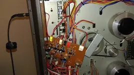
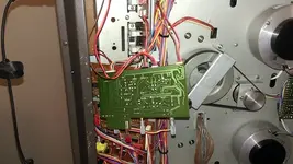
3. Measured voltage between pins 1 and 2 of P101 = 328 mV
4. Measure voltage between pin 2 of P101 and pin 3 of U103 = with phones knob cranked, I got 328 mV as well.
5. Repeated step 4 with pin 5 of U103 and got the same thing.
Hopefully this is more what you were expecting?
")