You are using an out of date browser. It may not display this or other websites correctly.
You should upgrade or use an alternative browser.
You should upgrade or use an alternative browser.
B
Bob's Mods
New member
The 2134 is your best bet assuming the existing chip is a dual op amp rather than the single variety. The 2228 appears to be an economy version of the 2134 and the 2604 would probably give you problems. The 2134 is usually a no brainer swap out in the audio domain. Be certain there is a .1 uF decoupling cap on the power legs.
Bob
Bob
crazydoc
Master Baiter
That's sort of strange, as the 2228 costs more than the 2134. It also has lower noise, higher GBW (though lower slew rate), CMRR and open loop gain. Which parameters are most important in this application?
B
Bob's Mods
New member
You are correct. They do cost more. I only read the data sheet when I made that call. The noise on all these devices is really not a factor as it is so very low you could not hear it's effect. The bandwith on both these devices is way more than needed for audio work as well. I am guessing that you probably couldn't hear the difference between these two ICs. Keep in mind these devices are used for other gear that may require extremely low noise and very wide bandwidth. Even if you were to record at 196k BW, these devices would have room to spare and then some.
The 2228 device does have a lower noise spec and wider bandwidth which would probably not provide improved performance in the tiny audio spectrum over the 2134. I'm not entirely sure about slew rate. I believe it is a measure of how much amplitude the output can change in one micro second which relates to accuracy. Larger values I suspect mean greater accuracy at high gain values. At 0 dB, the voltage should be about 800 mVpp if you were to look at it on the scope. For audio, you would not be pushing the output 20 v or 10 v. Maybe a volt tops. If your max freq is 20 kHz then thats 50 uS. You just won't be pushing the chip to the slew limit. It is a measure as to how dynamic a chip is, low values mean a dull, lifeless, compressive, less accurate chip. Maybe after 10v/us or some higher value, this number no longer matters for audio applications but below that you can certainly begin to hear this difference.
Another reason the 2228 might cost more too is that it uses less idle current so it would be great for conserving batteries on battery powered gadgets.
Lower noise, greater BW and less power consumption probably account for it's increased cost. Being that the 2134 is already fit for the job, having more of a good thing just won't provide any more sonic return for your money. That's my guess. The best test is an A/B test. Try the 2134 and then try the 2228 and record the results. There could well be a sonic difference between the two. The spec's state they are both contenders. I've been sticking with the 2134s but others on other newsgroups say they can hear differences among the better op amp devices.
crazydoc
Master Baiter
Thanks Bob - I really appreciate you taking the time to answer my goofy questions.
I got out the circuit for my M37 - it looks like the op amps need to be unity gain stable, so that would preclude using the 2228.
The M37 uses the OPA2107 - do you think the 2134 would be a significant upgrade?
I know, I know - try it and see.")
Also, the caps you replaced I assume are the ones connected to pins 2 and 3 of the xlr connector. Would you also replace the 100uF bypass caps at the hi-pass switch? (I'm assuming the M37 and M177 circuits are almost identical.) If so, what brand would you use?
Thanks again.
I got out the circuit for my M37 - it looks like the op amps need to be unity gain stable, so that would preclude using the 2228.
The M37 uses the OPA2107 - do you think the 2134 would be a significant upgrade?
I know, I know - try it and see.
Also, the caps you replaced I assume are the ones connected to pins 2 and 3 of the xlr connector. Would you also replace the 100uF bypass caps at the hi-pass switch? (I'm assuming the M37 and M177 circuits are almost identical.) If so, what brand would you use?
Thanks again.
B
Bob's Mods
New member
The data sheet for the 2228 does state that it is optimized for a gain of 5 or greater. That does not mean it won't work properly under that value but it is something to be aware of to be sure. Trying it is the only way to know. This is another reason I like the 134 series. They were optimized for audio! The other devices work with audio as a secondary application . If you look at the data sheet for the 2134 you will see that it states "Sound Plus High Performance". Other chips do not state this.
In the CAD M177, output A operates as a voltage follower where output B operates at unity gain so you make a valid point regarding stability.
In looking at the data sheet for the OPA2107, it looks like a respectable older device. Based around the data sheet alone, I would think you should not hear any improvement over what's in there now if you were to change to a 2134. I'm guessing the change would end up to be a wash but the only real way to know for sure is check it out with your ears. I've been satisfied with the 2134s so I have not been motivated to check out other higher end devices. There is no studying or testing. It just works better.
You may wish to download the PDF of the M177. It may still have a copy of the schematic on it. This schematic actually shows the 2107 chip although I found an 072 part in my M177 which is not as good a part. They've downgraded.
I changed the two .47 uF shunt caps (pins 2 & 3 on XLR) with caps I pulled from a large pile I have. I've collected an assortment of caps that I've stripped out of older scrapped out high voltage power supplies. You can find some high quality caps in power supplies. The caps I installed were a foil type that were small enough to fit in the limited space. They provided a nice boost in definition over the tantalums they used. I can't remember if the main 100 uF coupling caps were radial lead or surface mount, either way I left them. Shunting a smaller value high quality cap over a larger value lower quality cap is a valid trick for improving the performance of the cap when the larger value is impractical to change out.
crazydoc
Master Baiter
I downloaded the M177 manual
www.cadmics.com/pdf_files/m177_manual.pdf
with the schematic, but the schematic is too low a resolution to read the parts numbers. The circuit, however, is the spit and image of the M37.
www.cadmics.com/pdf_files/m37_manual.pdf
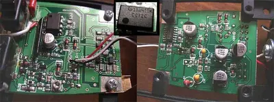
I got worried about the op amp so I opened up the mic and sure enough, it is a house numbered part I can't find on the TI website. So I guess I'll have to replace it anyway.
I've attached a composite pic of both sides of the board and the op amp. Lots of surface mount components. The tantalum caps in question are the yellow ones, in case anyone's interested.
I'm disappointed that CAD has downgraded the parts on their published schematics, at least in the case of the 177 and quite possibly the 37. (Although I'm glad they put the schematic in the manual - that's unheard of with mics.)
I guess I'll have to get DJL and the QC police on this right away.
www.cadmics.com/pdf_files/m177_manual.pdf
with the schematic, but the schematic is too low a resolution to read the parts numbers. The circuit, however, is the spit and image of the M37.
www.cadmics.com/pdf_files/m37_manual.pdf
I got worried about the op amp so I opened up the mic and sure enough, it is a house numbered part I can't find on the TI website. So I guess I'll have to replace it anyway.
I've attached a composite pic of both sides of the board and the op amp. Lots of surface mount components. The tantalum caps in question are the yellow ones, in case anyone's interested.
I'm disappointed that CAD has downgraded the parts on their published schematics, at least in the case of the 177 and quite possibly the 37. (Although I'm glad they put the schematic in the manual - that's unheard of with mics.)
I guess I'll have to get DJL and the QC police on this right away.
Attachments
B
Bob's Mods
New member
You ended up with same part I ended up with. No matter what they call it, I'm pretty sure it's just a Texas Instruments TL072 part. Not the best, not the worst. It's not as good as the 2107 would have been. The yellow caps roll off the lows in high pass mode. They are shunt caps in normal mode. These are audios absolute worst offenders of everything that is respectable audio. I was surprised to see them.
If you want to replace them, try and find a pure film polyester cap (non metalized type) that will fit in the case. You may have to do some rework, adding jumper wires, etc. to make this happen. These caps will have to stand off phantom voltage on the XLR side and +7.5 vdc on the chip side. The caps should be rated at least 40 v min.
Changing out the 100 uF surface mount main coupling caps with a Black Gate FK series cap would help alot too. I have never removed a surface mount electrolytic to install a thru hole radial cap so it might take some doing if it is possible at all. Working with surface mount is extra tricky.
junplugged
Taking the slow road
That clip sounds great.
I built stuff only from kits, so far. Designing is a whole different area.
I once found a site for building tube amps for guitar.
I wonder how much mod it would take for them to be preamps. Maybe they have preamps before the final amp stage....
I built stuff only from kits, so far. Designing is a whole different area.
I once found a site for building tube amps for guitar.
I wonder how much mod it would take for them to be preamps. Maybe they have preamps before the final amp stage....
D
dejacky
New member
how does this compare to the M-Audio DMP3? 
K
Kiauma
New member
Working with surface mount isn't that tough with a little practice. All you need is good vision - or one of those magnifying lamps - and two (2) fine chisel point 20W irons. With a steady hand it is not too hard to learn to 'tweese' components around with an iron in each hand like a pro.
crazydoc
Master Baiter
Wouldn't this tend to fry the active components like IC's and transistors? They can only take the heat for a few seconds at a time, and if you had two irons on them it would be even less.
D
dejacky
New member
that's great, but HOW does this preamp compare to the DMP3? 
K
Kiauma
New member
The two iron approach is generally for the resistors and capacitors. Also, it is extremely helpful to have a small board vise or other means of solidly holding your work.
Of course you would have to be careful with transistors, but in general if replacing a transistor it is not critical if you use too much heat to remove an unwanted one - just don't lift a pad. When soldering it back on use a pick to hold it in place then apply your iron quickly to each terminal in turn.
ICs are similar, but when removing I use small diagonal cutters to cut the leads, then clean off the pads with an iron. Again, when soldering on the new one, hold in place with a pick and carefully apply the iron to each lead.
Takes some practice, but doable with a few basic tools.
crazydoc
Master Baiter
Thanks, I'll give it a try. I've got lots of old boards to practice on.
P
paddyponchero
New member
Kiauma said:ICs are similar, but when removing I use small diagonal cutters to cut the leads, then clean off the pads with an iron.
You need a pretty good cutter and even then it's easy to pull pads using the diagonal cutters. Another option is to try to flood one side on the IC with solder, lift that side and remove excess solder. Then flood the other side and the chip will come right off.
This is a very successful method with SOIC's ( bit wastefull of solder and wick but far better than crapping track and pad repair )
For packages with finer leads a sharp scalpel is the best solution but don't let it slip or you go through all the tracks and maybe your hand.
Low budget manufacturing and repair shops use a temperature controlled heat gun for large parts including BGA's (like one you'd strip paint with but with a thermostat) With careful use you can do anything surface mount with one, you can also blow every part around the board if you're not careful.
K
Kiauma
New member
Whatever works.
Here is an interesting link;
http://www.gyraf.dk/index.html
Click on the "DIY-projects" link in the left frame. Very interesting.
Also, here is where you can buy the Lundahl transformers;
http://www.kandkaudio.com/
Here is an interesting link;
http://www.gyraf.dk/index.html
Click on the "DIY-projects" link in the left frame. Very interesting.
Also, here is where you can buy the Lundahl transformers;
http://www.kandkaudio.com/
B
Bob's Mods
New member
I gave this thread up for dead but it seems to have sustained life. Interesting stuff about reworking surface mount. It is still more of a bother to work with than DIP stuff which preceeded it. It does take some practice and if components are too close it can be really tough. This stuff is designed for reduced real estate and repair of it is an after thought.
Surface mount and DSP related parts are not designed to be repaired for the long term. When it breaks its dead. The world of digital components changes too fast and older parts cannot always be found for repair and compatible parts may not exist. If the manufacturer does not want to service it any longer you'll be out of luck depending on the nature of the problem. The rule of thumb for repairs of todays gear is seven years, after that its up the manufacturer.
These days, the newer, digital based, plastic cased stuff with surface mount won't be the vintage gear of tomorrow. When it dies, you won't be able to reverse engineer it to make it work again. Manufacturers want this stuff out of the pipeline and want you to consider new gear. Vintage is vintage. If you can see the components without glasses and its analog, then you can probably fix it for a long time.
We live in a world of throw away electronics now.
F
Flatpicker
...
Since the DMP3 uses a capacitor coupled input straight into the op amp, Bobs transformer coupled input version should sound much better, especially given the fact that he used a Lundahl transformer.dejacky said:that's great, but HOW does this preamp compare to the DMP3?
B
Bob's Mods
New member
Typically, only your most expensive mics and preamps will use transformers, everyone else uses very cheap capacitors. You will see some transformer coupled stuff, Oktava Mk-319 and some of those MXL mics, but these xformers are of a cheap variety and should not be confused with Lundhal or Jensen.
There are ways of reducing the problems capacitors cause. For those of you interested in the problems of capacitors there is an excellant talk on this by John Hardy on his web site. You will find it as a PDF file for his 990 op amp on p5 or 6. An interesting read for the technically inclined.
There are ways of reducing the problems capacitors cause. For those of you interested in the problems of capacitors there is an excellant talk on this by John Hardy on his web site. You will find it as a PDF file for his 990 op amp on p5 or 6. An interesting read for the technically inclined.
Similar threads
D
- Replies
- 19
- Views
- 4K
D
- Replies
- 4
- Views
- 935
- Replies
- 0
- Views
- 10K