Velvet Elvis
Ahh humma humma humma
Those math calculations make me want to vomit ")
I'll be patient, Rick.. thanks for your work!!
Jim
I'll be patient, Rick.. thanks for your work!!
Jim
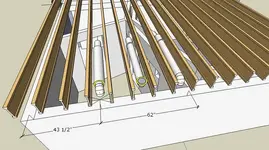
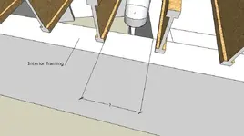
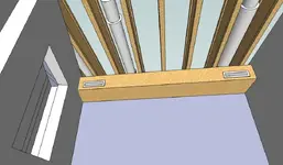
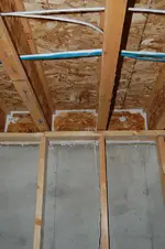
 One more thing. I need a dimension between the centerlines of the two joist cavities that contain the 2 ducts. In other words, from centerline of one cavity to the other. 16" o.c. don't always work out. I need reality.
") Oh, and measure it at where the baffle is going. Things aren't always plumb, square, level etc. Except when I build things.
Oh, and measure it at where the baffle is going. Things aren't always plumb, square, level etc. Except when I build things.Rick,
that isn't anything you want to use with this - all of this is based first on a decrease in velocity - and the baffles are next - the absorbing interior is minor - and we definately don't want to get involved in tuning tubes for these purposes.
Rod
You're the expert.Ok, sounds good to me.that isn't anything you want to use with this
That reminds meSo is this saying that any old baffle that allows the air velocity to decrease (by increasing volume) and contains some 90 degree bends in it will do the trick?
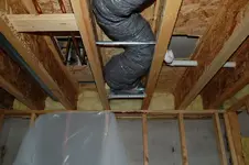
 what diameter is your flex ducting?
That reminds me
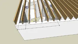
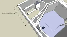
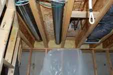
 In fact, if you can also give me a dimension from the exterior wall parallel to the joists, to the centerline of the closest joist cavity with the flex duct, I'd 'preciate it.
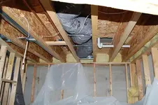
 Let me explain. And further to the left, right at the corner(which is obscured), I can barely make out what appears to be another duct, which I ASSUME, by your dimensions, MUST be the RETURN for the drum room.
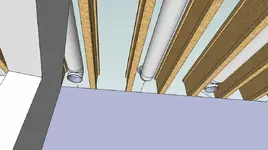
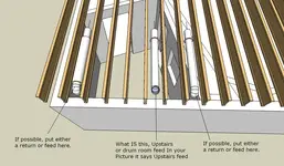
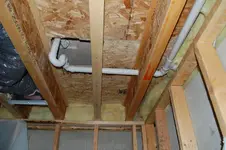
See my drawingThe one that you assume is a return from the drum room is actually a feed to the second floor of the house...The return in the drum room has not yet been placed, so it can go anywhere.In that obscure corner?
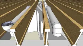
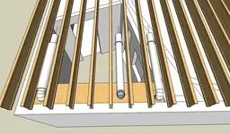
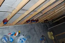
The feed to the drum room is rigid pipe right now, from pre-existing work in the basement, but I plan on changing it to flex and will have the ability to move it over a few trusses if we want.
NO WONDER! Then WHAT is the flex line in the middle of the drum room?? To the upstairs? Actually, here is what would be ideal.