New owner of Neotek Series III. You guys weren't exaggerating about the level of commitment.

  • Thread starter Thread starter AnalogApples
  • Start date Start date
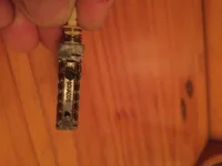
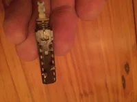
Update: I got it plugged in. Mmm that sweet smell of burning resistors! I found a several resistors near my TL074CN chips blackened. The chips were installed backwards. Yikes. So I replaced those resistors and they're no longer burning up. I got to work reseating opamps. Check out how grody these chips are! I cleaned them with a tiny wire brush and reinserted. So far, I have 19 out of the 24 channels working. Seems like these big clunky switches are also dirty inside, as many of the channels crackle to life when i wiggle the switches.

I'm testing voltages going to all the IC chips. So far most of them have 7-8 volts going into them. Not sure what I'm looking for. I'm going to have to learn how to verify if an IC chip is working since theres about 15 per channel, plus 4 per channel in the meter bridge. I contemplated just rechipping the entire board, which I think I may be able to do for about $300. Are IC chips straighforward to test?

Edit: I just ordered an OP-amp testing PCB board from ebay. It has a 12V power supply input, and 8 LEDs for each chip socket, apparently it tells me if it's working, and if the bandwidth is in spec.
78728204856__D84A393D-8083-4FC6-B854-D9E9F7074548.webp
IMG_2809.webp
2flipped.webp
 
Last edited:
So the TL074…it’s a stable chip…the TL07x series gets an undeserved bad rap.

On the TL074 you should have, if I’m reading the schematics correctly, about +18V on pin 4, and about -18V on pin 11 relative to ground for the +/-18V audio power rails.

Those PC pins look…nasty…if the IC looks like that the socket can’t be good. Verify power, and if it was me I’d probably be replacing the sockets with new machine pin type sockets. That console is worth doing it right. The sockets aren’t expensive.

Post a pic of the switches.
 
Op amps can usually work from +/- 5V to +/-15V. Depends on the chip. Get the data sheets, they are available.
+/-18V is probably the high end.
If you're going to replace the chips, don't solder them in.
Plug them into gold plated turned pin sockets. They cost a bit, but they're worth it down the line.
 
TL074 is rated up to 40V power input (so up to +/-20V bipolar), at least the TI version.
 
I haven't dug up the voltage spec for those IC chips. Mike Stoica says they deliberately tried not to get too much gain out of the opamps because he says it preserves the tone better. Makes me wonder if that's done by decreasing the voltage they're run on.

These are the switches used with the input module. They are SHADOW brand. The Neotek Google Group says that some/all of these Shadow switches were recalled by Neotek in the 80s. Mike Stoica, the CEO of Sytek (Neotek) says that his techs used a cleaner called Sabilint 22. He says they were able to rescue almost all the switches they used it on. Drop it in the top of the switch with a syringe. A Neotek tech was emphatic that an amateur should not attempt to replace these switches because you can damage the board.

I haven't done any further testing or trouble-shooting of the console because I need to solder up an XLR female wall panel so I can actually plug a balanced mic into the console.
I'm already thinking of mods I can do to this board. My Tascam allows me to send two sources to the 2 mix. So I can use one channel as a mic/line pre, and as an effect return at the same time, using a mini-fader. The Neotek seems set up to do this, and it might already do that, OR the logic mutes all but one source on the channel strip.

Either way this is so much more fun than doing a 2,000 piece puzzle!
 

Attachments

  • IMG_2834.webp
    IMG_2834.webp
    805.7 KB · Views: 34
  • IMG_2835.webp
    IMG_2835.webp
    728.2 KB · Views: 34
Gain is not a function of the power supply that powers an active device. In this case power supply voltage determines headroom. What sets the gain is the resistors associated with an amplifier stage, particularly the resistor in the feedback loop. You should have about +/-18V at the respective positive and negative power inputs of the TL074s; pins 4 & 11.

Schadow switches…this type of switch was very commonly used in all sorts of equipment, and yes they wear out or become oxidized. It is not an uncommon practice to re-switch a console. You can try and limp them along with a contact cleaner…certainly try that first. But replacing with new switches is a guaranteed fix. I noticed the boards are phenolic resin type boards, so yes some greater care needs to be taken when replacing components, but it’s not like “don’t touch it”. If you have experience with board-level repair these boards will be like anything else. There’s just some skill needed with multipin components. Good equipment helps. And some experience.
Thank you for the encouragement. I'm learning so much! I'm guessing this tech saw some switches replaced by beginners and the traces probably got shredded, like the guy didn't fully desolder them before trying to pull it out---I used to do that as a teen before I discovered solder suckers and solder braid. The guy I bought this from included a manual solder sucker made from aluminum. It's SO MUCH better than the cheap plastic one I was using, almost a different tool entirely!
 
Back
Top