Tascam 58-OB Story...

  • Thread starter Thread starter sweetbeats
  • Start date Start date
Um...yeah...pull the PS connector...um...there is no master connector...so I chase down where all the wires go out of the PS and pull those connectors right? I'm looking at pages 8-36 and 8-37 in the manual for that overview...problem is that the wires that go to the two JOINT PCB assemblies don't have disconnects on them...they are hard-wired from the PS. Do I have to desolder the wires then to isolate the PS and test? And I'm assuming I'll need to find some more fuses for F2 and F3, and if they blow then the place to start is definitely on the PS PCB assuming the PS is isolated right?
 
Darn, soldered....

Yes, 8-36/37. Looks like you can unplug them on the destination side.

--Ethan
 
I found all the destination points except the capstan PCB...I think it is internal and I'm not too interested in pulling the capstan motor and opening it up...it has been running fine and I'm inclined to leave that be.

Pulled three connectors on the Control PCB assembly, one on the Interface PCB assembly, one on the Mother PCB assembly, and there is a sub PS assembly for the balance amp...small connector that goes from that to the I/O amp PCB, so I pulled that too. Couple fuses on it as well...the check out ok.

SO...the capstan motor is still gonna be powered, but I'm not sure how to tell if it is okay because it won't be getting pitch control info from the Interface PCB...dunno if that information only comes into play if the deck is set for external sync or if pitch control is engaged...any quick answers on that one? Nd the Joint PCB's will still be powered, but no cross-connect with the Control PCB...

Not mentally ready to switch it on...

Saw a cooked resistor on the Mother PCB tho'...
 
That's a tough break, man!

Aaaggghhh!!! You cross-connect something and you really don't know what you'll end up with! I feel your frustration. :eek:;)
 
Thats good

Given that you were seeing different voltages based on which slot I wold expect a fried resistor (at least) on the motherboard. Fried is good. It is the ones that you cannot see that are hard to find.

Also, it gives you more of a clue as to what to look at next... I assume that it is R5.

-Ethan
 
Ethan, Do you think I'm good to power up the deck to test PS voltages even though the capstan motor is still connected (although the pitch control is interrupted via the disconnected P4 on the Interface Assembly), and the Joint PCB boards are still connected (though there are connection interuptions via the disconnected P10 on the Control PCB)? I just don't want to risk damage to anything that is still partially connected.

If you're not sure or are short on time then I may just cut the soldered lines and crimp them back together after testing...

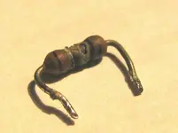
Yes, Ethan, it is indeed R5 that is scorched! :eek: Again, as an individual that values humility you probably think its nothing, but it is amazing to me that you, amidst a busy job, and big projects of your own (i.e. MS16) have the talent (and take the time) to be able to deduce that kind of stuff. I really wish I could do that.

Do you or does anybody know anything like an electronics wiki that goes over some basics of SM and IC component functions and a beginners guide on how to read schematics and such? I can stumble my way around, like I can follow the paths but I lack understanding on what is really happening as I follow the trail.

I'm not suggesting/thinking that a wiki-esque resource is going to be a replacement for real-world experience and/or accredited education on the subject, but I'd like to learn. This stuff is like a puzzle...the schematic...and when there is a problem with something it can be a really fun activity to solve the puzzle...quantify a symptom or symptoms, study the schematic, deduce, test the theory, and then that may be the fix or the fun may continue...it may be a multi-step puzzle.

I didn't used to like puzzles when I was a child...I was too impatient, but over the years I have really, really grown to like them whether it be a jigsaw puzzle, or I remember when my wife bought the computer game Myst for me...multi-step puzzles...my daughters love tangling strings...they like to tie knots in stuff and pretty soon there is a mess but I really enjoy untangling it.

My point is that it would be fun and valuable to know more about how to carry out deductions from the schematics...to participate in the community problem-solving like you and others are doing...not anticipating I'd ever get to your ability level and/or the levels of many, many others around here, but I'd love to get away from totally losing the trail as soon as I hit the first SM or IC component on the schematic y'know? Much of it is a foreign language.

  • I know what resistors do and how to determine their value from the color bands.
  • I know what diodes do.
  • I think I understand what a capacitor does but I'm not certain how or what the effect is...Its like a little current buffer?
  • IC's...forget it.
  • Rectifier...no clue

So anyway, blah, blah, blah.

I'll keep working on it.
 
jpmorris,

Cool. Thank you. That does make sense, and it also helped me learn a little something about diodes...I've only dealt with using diodes in a project where they were used on the positive side of the circuit. I didn't realize that the diode ensures a positive current flow only goes in one direction, and ensures that an associated negative current can only flow in the opposite direction.

Is my understanding correct?

Maybe wikipedia would be a good place to read up on other electronic components...
 
Electronics 101 #1

I’m going to ask a bunch of questions here, hoping for as much response as I can get but respectful of everybody’s time...this could probably be another thread elsewhere, and maybe it already has :o, but it is directly related to my 58 story that it is goin' here…I know some of these questions are basic stuff, but they remain dubious to me and the only way I can see fit at the moment to start figuring it out is to put it here, so here goes….

The electrical currents inside the 58 are all DC…so it’s a one-way stream right? Can somebody help me understand what the whole –VDC deal is? The power supply includes a +15 and a -15V rail for instance…what does the “-“ mean in relation to ground? I guess I just don’t understand how/where the electrons are flowing in a minus value DC circuit…is it a polarity thing? This is nagging my brain because I’m trying to understand the current flow in and out of the 25 connector pins on the amp card…trying to understand what collided/shorted when I installed my #8 amp card incorrectly. Ethan, I know you commented on that already and clearly have an understanding of what potentially occurred; I’m just trying to catch up to you rather than say “Okay thanks…what do I do now?”

Please look at the jpeg attached below of the input/output connections on the 58 amp card. I’m going to take a crack at understanding the current inflows and outflows. Correct me where I’m wrong, fill in the blank where I’m clueless. “In” and “out” are with respect to the card (i.e. “in” means current flowing into the card, “out” means current flowing out):

Pin 1 in
Pin2 out
Pin 3 in? Do the ground circuits for the heads go back through the amp cards? It appears so according to the amp card schematic, but I want to confirm if that is right…I'll put up a schematic if needed...
Pin 4 ??? Its that negative voltage thing…
Pin 5 out
Pin 6 out
Pin 7 out
Pin 8 out
Pin 9 out
Pin 10 out
Pin 11 in
Pin 12 in

Pin 13 in?
Pin 14 out
Pin 15 in?
Pin 16 in?
Pin 17 in?
Pin 18 in?
Pin 19 in?
Pin 20 in?
Pin 21 in
Pin 22 ???
Pin 23 in
Pin 24 out
Pin 25 in?


Transistors…What is the best way to understand what they do? I haven’t tried this yet, but would doing a web search of the description for a specific part likely turn up some helpful info?
 

Attachments

  • amp card i-o.webp
    amp card i-o.webp
    24.6 KB · Views: 76
Last edited:
Where do we go from R5?

Ethan,

Given that you were seeing different voltages based on which slot I wold expect a fried resistor (at least) on the motherboard.

I thought the different voltages were related to the fuses burning up, or is that what you are saying? That, since a fried resistor will not do what it is supposed to do (decrease voltage right), and depending on a particular circuit, if a resistor is fried then when new fuses are put in the bad resistor is allowing too much current to flow and it will overload the fuses and burn them up? And in my case it took the amount of time from testing the connections on amp card #8 'til amp card #5 before the fuses burned?

Fried is good. It is the ones that you cannot see that are hard to find.

Also, it gives you more of a clue as to what to look at next... I assume that it is R5.

So, okay. I'm looking at 8-42/43, the Mother PCB schematic. The amp card was offset one pin to the left as it is shown on the schematic. So pin 12 +24 was not connected to anything on the amp card, but the +24 trace on the Mother PCB also goes to R5, and then to the peak LED, which goes back to the amp card pin 8. On the Amp Card schematic (8-40/41), pin 8 goes to a transistor, Q14. That's where I get lost...transistors...

Okay...wait...So is it like current flows into the amp card through pin 8 (not out like I thought above) and then it gets to R117 which makes sure Q14 doesn't get overloaded, D7 is a gate that makes sure the current doesn't go upstream past Q14, and, based on the setting of R210, if the current on the upstream side of D7 reaches a threshhold Q14 dumps to ground, the circuit is completed and the peak LED lights?? And until that current level is reached R117 just soaks it up? There's a bunch of other stuff in there (U2/2 for instance) that I don't understand, but do I have the basic idea of how the circuit works? And by offsetting the pins +24VDC from pin 8 shot straight up trace 9 and went straight to C28, a 10V cap right? It would have run right over that 10V cap straight to ground and the peak LED would have lit up good and solid, which it did, and then the meter out on pin 9 would have been connected to trace 10 which...would have...uh...I'm going to stop there for now...I'm getting confused...:confused:

But when the deal went down it was only meter #8 that was pegged and the peak LED lit...
 
Looks like you will get more out of this than expected....

Good to turn it into an educational event.

I'm getting a sailboat ready for a run up the coast to the San Juans. So, I might be late in getting back to you (like today).

diodes and rectifiers are the same thing. They can be for power or for "small signals". Diodes pass current in only one way. Thus they convert AC to DC. You can wire them alone, "half wave", in pairs with a split transformer, "full wave" or in 4s for a "bridge" rectifer.

Lets take a transformer that converts the 120 AC wall current to 15 volts. This is a sine wave at 15 volts. Hook that scope to is and you will see that half the waveform is above 0 volts and the other is below zero volts. Take one side of the transformer and hook it to ground and you will still see half the voltage about 0 and half below 0.

Now put a diode in the circuit. Hook the scope probe to the diode and you will see that the voltage is only positive. Turn the diode around and measure again and you will see only negative voltages.

Think of it like a battery. Hook the negative of the battery to ground and you have a +12 (OK so it is a car battery). Now get a second battery. Hook the positive terminal to ground and measure. You get -12 volts. Measure from the + terminal of the first battery to the negative terminal of he second battery and you have 24 volts.

Don't think in terms of coming from (+) or going to (-) voltages. This is just the direction of the electron motion. It still comes from the battery or power supply. think of it as a circuit as in loop.

There are some nice electronics courses on the internet. Expect to be confused for a while. That is normal.
 
THe + 24 volt supply for the peak led's can supply amps.... R5 limits the maximum current to 888mA and there to burn out if there is a problem....

This (limited) 24 volts goes through the LED (which only need a few mA to work) and into the rec/repro card. It then goes through r117 (4.7k) which further limits the current for this specific led to 5 mA ...24 / (4700+27) = 0.005.

Q14 is normally off so the voltage on the led has nowhere to go and the led is off. When Q14 is turned on the current will flow through the led and the current will be limited by the total resistance (r5+r117+ the transistors "on" resistance)

So r117 does not protect Q14, rather it sets the LED current.

By offsetting the card the +24 volt LED supply (limited to 888mA by R5) was shorted to ground through the LED (which may never be the same) and the meter (which may Never be the same again)

This part is small potatoes. the resistor burnt because is is likely a 1/2 watt resistor and 24v * 888mA is 21 watts.

I would say that you "should" be OK in powering up with Capstan board connected. What I'm looking for is if there is a problem with the Power Supply. If it blows fuses with nothing connected then there is a PS problem.

Next step is to pull all the channel cards and reconnect connectors one at a time. Power up and then check fuses after reconnecting each one. Here you are looking for bad subsystems

Then if no fuses blow. Install the channel cards one at a time and powering up and rechecking fuses. Here you are looking for bad channel cards. I would assume that channel 8's card is bad....

Actually the first thing is to locate all the burnt/bad parts that you can see and replace them (R5) .

I'll help as I can but I'll be offshore starting Friday evening till Thursday.

Take your time and be methodical. You will be able to fix this.

--Ethan
 
Diodes pass current in only one way. Thus they convert AC to DC.

Oh cool! I get it! And they are also used to direct current flow right? Like with D7 right next to Q14...right?

Lets take a transformer that converts the 120 AC wall current to 15 volts. This is a sine wave at 15 volts. Hook that scope to is and you will see that half the waveform is above 0 volts and the other is below zero volts. Take one side of the transformer and hook it to ground and you will still see half the voltage about 0 and half below 0.

Now put a diode in the circuit. Hook the scope probe to the diode and you will see that the voltage is only positive. Turn the diode around and measure again and you will see only negative voltages.

Ah! So both sides of the transformer have the potential to do work. So is it safe to say that having a dual-rail PS is, in part, a matter of efficiency? Using all of what is there?

Think of it like a battery. Hook the negative of the battery to ground and you have a +12 (OK so it is a car battery). Now get a second battery. Hook the positive terminal to ground and measure. You get -12 volts. Measure from the + terminal of the first battery to the negative terminal of he second battery and you have 24 volts.

Oh, oh, oh! When my dad and I used to work on old British cars, I recall now we had to be cautious of cars with a positive ground system; the proper components compatible with a positive ground system had to used and of course the wiring hookup had to follow suit...I keep making the mistake of confusing ground with the negative terminal. Ground completes the circuit...the loop...in a DC circuit, right? And whether electrons enter the circuit from the negative or positive side of the battery is of little consequence...

This (limited) 24 volts goes through the LED (which only need a few mA to work) and into the rec/repro card. It then goes through r117 (4.7k) which further limits the current for this specific led to 5 mA ...24 / (4700+27) = 0.005.

Okay...So a resistor creates a voltage drop on both sides...? By inserting R5 in the 24+ supply the current becomes 888mA on the upstream and downstream side, and then R117 further reduces the current to 5mA on the downstream side and also between it and R5 (which includes the peak LED)?

Q14 is normally off so the voltage on the led has nowhere to go and the led is off. When Q14 is turned on the current will flow through the led and the current will be limited by the total resistance (r5+r117+ the transistors "on" resistance)

So r117 does not protect Q14, rather it sets the LED current.

Okay. I see that now. That makes sense. There is no current to 'soak up' because there is no current flowing when Q14 is off...path of least resistance...off is infinite resistance, electrons won't go down that wire...

By offsetting the card the +24 volt LED supply (limited to 888mA by R5) was shorted to ground through the LED (which may never be the same) and the meter (which may Never be the same again)

Right, right, right...I get it. There was nothing to slow the flow down (i.e. R117) when the peak LED circuit on the Mother PCB connected with trace 9 on the amp card and I see it goes straight to ground. Just for te sake of education, what did that likely do to C28?

I would say that you "should" be OK in powering up with Capstan board connected. What I'm looking for is if there is a problem with the Power Supply. If it blows fuses with nothing connected then there is a PS problem.

Right. It will be a little stickier if fuses still blow with the capstan and joint PCB's still partially connected. I just don't want to further damage anything. If fuses blow I'll have to take some extra steps then and get those disconnected...pull the capstan motor and clip the wires to the joint PCB's. Basic troubleshooting at this point then. I do this with recalcitrant computers at work...pull everything and replace one at a time cycling power in between until you find the component that sets things on its ear. ;)

Actually the first thing is to locate all the burnt/bad parts that you can see and replace them (R5) .

Yes. :) And get a bunch of fuses. :D Anybody have any comment on whether or not Radio Shack is a good place to get surface mount components such as resistors? They are the only electronics shop with such stuffs in town...

As always, thank you, Ethan. This is extremely valuable, and I hope it is helpful to others as well.

I'll be cognizant of your trip at sea (hope all goes well). My client had to reschedule, so that has worked out well to buy some time.
 
Last edited:
Wow, I'm getting some education here as well.... while I can operate a soldering iron fairly well, I am NOT the world's greatest electronics tech. I DO know that there is nothing inherently wrong with the resistors and such sold by Radio Shack, they have a limited list of parts and tend to be rather pricey. CHeck your codes and make sure you get the proper parts.
I will be sure to post and beg for help when I get around to trying to repair the Revox..... it's just very low on my list at the moment, heck I can't even find the time right now to finish the calibration on the Otari..... thinking I have a major jobh realigning the heads on that unti before I am goibg to get anywhere (subject for aniotehr post).

Just keep plugging away Sweetbeats, you will get it working!


AK
 
Thanks, AK.

Yeah, I know I'm going to pay premium at RS, but it is cheaper than driving the 40 mile round trip to my favorite shop in the next town...I'll go there when I get a bigger list going, but as of yet the only compenent I can see that is cooked is resistor R5 on the Mother PCB...might not be able to get it at RS tho'...27Ω 5%, 1/4W I think...The manual doesn't state the wattage value, and I called Tascam and they thought it was probably 1/4watt but told me to confirm by the size...so now I'm going to learn how to identify resistor wattage by the size...

Anyway, I know there will be more components to replace, but that one is charred. :o
 
The victim has been excised...

Good news! I powered the 58 up with all disconnects from the PS pulled and no fuses blew! :p Left it powered on for about 10 minutes or so...figured that was a good test.

Pulled the Mother PCB out to get R5 off the board...it is aptly names "Mother", as that's exactly what it was to remove it...47 connections to remove I think, and many of them zip-tied together in spots that were hard to access in order to clip the ties...I thought about trying to desolder R5 through the card-bay, but thought better of it. And by the way, I can really see why the RCA jacks are an achilles-heel on the 58. It is a crazy design. The PCB itself is mounted to the frame with 9 screws I think, which is a good thing since its gets the abuse of amp cards being pulled and reinstalled, and it is further supported against the back cover panel by...you guessed it...the 8 platforms that hold the RCA jacks. So in a sense the pieces that hold the RCA jacks also supports the PCB when installing cards and that thing is held to the PCB by nothing other than the solder joints for the jacks. :eek:

Here is a pic of the current state of the 58:
58%20Status%202008%2008%2007.JPG


Went to my fav electronics shop instead of Radio Shack...Had some other stuff to pick up. Looks like size-wise the resistor st R5 is indeed 1/4watt. Got a pack of those and got the burned up one out without a problem. I'll be putting a new one in sometime in the next day or two and then I'll get the Mother PCB back in and start connecting sub-systems up and seeing what blows. Oh yeah, got a bunch of fuses too. :p;)

Here are pictures of the victim of my carelessness, and its former home...
 

Attachments

  • IMG_7719_1_3_1.webp
    IMG_7719_1_3_1.webp
    25.3 KB · Views: 63
  • IMG_7718_1_4_1.webp
    IMG_7718_1_4_1.webp
    20.4 KB · Views: 64
Awesome

Ah, movement forward.

Looks like 1/4 watt to me....

So now you know that the PS is good (no blown diodes most likely) and that the capstan board is also good.

As you reconnect subsystems and smoke test them (a technical term - really!) Look, listen and smell for anything out of the norm. You could also hook that meter up the the +15 (or any supply that blew the fuse before) and if it does not go straight to 15 then power off. If for example it is running at 10 or 12 rather than 15, something is pulling it down. Some bad thing. Just a test that may offer an early warning.

Hopefully you will find that any damage is limited to a channel card or 2 and the rest is good. I do have my hopes. So, pull all the cards and test those subsystems with no channel cards installed. then install them one by one saving 8 for last....

Good work!

--Ethan

should you find a bad subsystem let me know and I'll look through the schematic and see if I can make a guess as to what is toast.
 
:D:D:D

Thanks, Ethan!

I guess I should check the voltages at the PS before hooking up sub-systems. I didn't do that...I just made sure the fuses remained intact. I'll do that to get a feel for what is producing what unloaded and then look for changes on the rails that correspond to fuses F2 and F3 as I connect systems...after I stuff R5. :p
 
Finding differences is half (pun!) the battle

:D:D:D

Thanks, Ethan!

I guess I should check the voltages at the PS before hooking up sub-systems. I didn't do that...I just made sure the fuses remained intact. I'll do that to get a feel for what is producing what unloaded and then look for changes on the rails that correspond to fuses F2 and F3 as I connect systems...after I stuff R5. :p

Yup! That is what I would do.

-_Ethan
 
Back
Top