Tascam 58-OB Story...

  • Thread starter Thread starter sweetbeats
  • Start date Start date
OK, I uploaded the 3 video files (part 1, 2 and 3) here:

Guys, please take a few moments to download the files and provide some input. We need discussion here, dammit!:mad::eek::D;)

---

Looks like you have to join up to view the files. Is that right ??

Sweetbeats,

Where'd you go ? I have been a member here for quite a while but have never found much to talk about.
 
sweetbeats said:
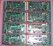
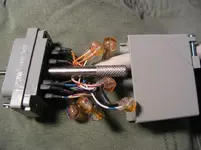
I pulled my rec/repro amp cards last night and visually inspected them and dribbled deoxit on the multi-pin connectors, seated and re-seated. I then proceeded with the overall record frequency response calibration.

As the manual says to do I started with the repro head (e.g. loaded blank tape, connected +4dBm test signal, recorded 40Hz, 100Hz, 1kHz, 10kHz and 20kHz test tones on each track while monitoring the repro head and watched the level response to ensure that it was between +/-3VU for each track at each frequency). After a little tweaking of the hi and low record eq pots (R208 and R203 respectively) I was within +1 ~ -1.5 through the test range. I had some problems with track 6...at first I was getting *totally* unstable response...the level would start at -1 and slowly drop to -6...I'd stop and try it again and it would creep up and then drop down...I reseated the amp card...same thing...swapped cards for channels 5 and 6 and the problem followed the card. Then I tried gently manipulating the card while recording and was able to get it stable by gently applying pressure to the right at the bottom of the card. It was stable without pressure after that. Hmm...don't like that.

Then I did the sync head (e.g. same procedure but record the tones while monitoring the sync head and then watch the response on playback. This was all A-OK (which it should be after making the adjustments on the repro side), until 20kHz...I'll attach some video files shortly.

Basically, when I put the 20kHz test tone into the 58, as I should expect I'd see the tone on the channel VU (let's say channel 4 in this case) when monitoring the sync head with the transport in stop mode. With the track in rec ready mode, as soon as I put the transport into record status the VU meters of the adjacent channels would show signal as well (channels 3 and 5 in this case), even if the adjacent channels had not signal physically connected!

Then I noticed this issue was present at 10kHz as well, but only with slight meter deflection on the adjacent channels.

What does this mean??

When I'd record the tone, the adjacent channel VU meters would show very unsteady levels, even when signal is already recorded on those adjacent tracks. On playback though, everything is totally fine...stable, isolated, etc. So the VU's are (fortunately) not showing what is being printed to tape, but I'm thinking this is going to need to be resolved before I take this thing into session.


How stable should I expect the meteres to be when monitoring playback? Between the repro and sync heads I've got some tracks that are rock steady at most frequencies, and some that are wavering a bit all the time at certain frequencies, and a few that are varying some (but less than a 0.5VU range) on for certain frequencies. Is this normal, or is it a sign that something is not right (i.e. should I expect all tracks to be rock steady over the test spectrum)?

I finally got a chance to look over your post and the videos (now that they’re all working ;) ).


METER CROSSTALK ISSUE
Some interaction is to be expected while in sync mode at high frequencies and it only affects the adjacent meters, not what goes to tape. The higher the frequency, the greater the deflection at a given level. The phenomenon varies depending on the machine.

The first thing to keep in mind is this won’t cause any problems during real world recording… at least it shouldn’t if there’s nothing wrong with the machine. This is because when recording music the only thing that lives near 20kHz are upper harmonics and they are nowhere near what you’re hitting your meters with in your test.

A couple other tests you should try to confirm this:

1. Perform the same test with track 6, but also set record enable on tracks 5 & 7. Make sure you only have signal going to track-6 just like before. At 20kHz the deflection on the adjacent meters should be much less (maybe none at all).

2. Also do the same test with music from a CD or other source instead of a test tone. With music peaks around 0VU the adjacent meters should not be moving.

3. If you’re still seeing more interaction between the meters than you should, try connecting the outputs from your mixer to the corresponding inputs on the deck (except the input from the oscillator, of course), then perform the tests again. When you have the inputs (or outputs) disconnected (floating) it may allow spurious signals to affect neighboring components such as adjacent meter circuits. Even with all the faders down on your mixer the circuit for each channel is still complete and more resistant to interference.

Also keep in mind that recording a high frequency test tone while playing back another on an adjacent track has no real practical utility. You want to record each track and then play them back together (or one at a time) to get a picture of the machines frequency response. So while the meter interaction may be annoying it’s only a problem if it occurs while overdubbing during multitrack recording of music.

AMP CARD ISSUE
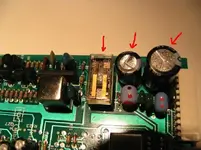
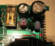
It’s usually the little things with the amp card. The contacts on both sides get oxidation buildup, bad capacitors and/or bad relays.

Sometimes DeoxIT isn’t enough, so try a fine brass wire brush (about the size of a large toothbrush) along with the DeoxIT. You can get them at hardware stores or in sporting goods departments that have gun cleaning supplies.

The relays on your amp card are the non-sealed type, so they will get oxidized. The clear plastic top lifts off so you can clean them with DeoxIT as well. It’s best to replace them with a sealed type, but cleaning them will give them some more life. When cleaning relays, apply DeoxIT and turn card upside-down right away, as these cleaners can damage some plastics.

The two electrolytic capacitors right next to the relay are more likely to fail than others, so you may fix your problem by changing only those.

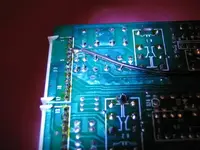
One final note on the cards – a lot of manufacturers during 80’s and 90’s coated the solder side of circuit boards with a spray that was supposed to protect the traces and solder points from corrosion. Only trouble is this substance ended up breaking down over years and became conductive. It can cause all kinds of buggy ghost-in-the-machine behavior that will have you pulling your hair out.

I remove it with another gun cleaning product called Birchwood-Casey Gun Scrubber. Only try this if all else fails to fix the buggy amp card. You can usually detect this problem if the circuit board feels tacky or sticky to the touch.

You hold the circuit board in one hand so the edge faces the ground (wear rubber gloves) and spray the solvent onto the back (solder side) of the board until all of the sticky brownish residue has run off. Don’t spray it on the component side or get it in any pots or trimmers.

METER PLAYBACK STABILITY QUESTION
It’s normal for the meters to flutter a little, especially on edge tracks with high frequency tones. This is true whether recording tones with a blank tape or using a calibration tape by MRL, TEAC, or STL. You’ll see the needle move up and down… a half dB is typical, but it should be smooth, not jerky. In J. McKnight’s warranty for MRL tapes it states the amplitude must vary up and down by more than 1dB for the tape to be considered defective. It also depends on the condition of the machine.

A really important thing to understand is that tracks won’t necessarily behave exactly the same on the same head… there will be variation within manufacturer specs.

:)
 

Attachments

  • T48b.webp
    T48b.webp
    33 KB · Views: 476
You're welcome Daniel. ;)

By the way, I forgot to mention something in my posting frenzy... cold solder joints. On those types of amp cards you may encounter “broken” solder joints where the pins connect to the board. It will cause intermittent problems. Since one of the issues seems to follow the card I should have mentioned that.

It’s an easy fix – just turn the card over so the trace side is facing up and touch a soldering iron to each pin until the solder around it liquefies. (There are traces and solder points on both sides of that board, but heating the tip of the pins on the bottom side should do it)

Adding a little solder won't hurt.

:)
 

Attachments

  • T58pins.webp
    T58pins.webp
    20.6 KB · Views: 502
Last edited:
Looks like you have to join up to view the files. Is that right ??

If you're not a member of rapidshare you just have to wait a few seconds and can only download one file every 8 minutes, but I got around the 8 minute thing simply by clearing cookies and temporary files in IE.

Click on free download and it will walk you through.
 

Attachments

  • free.webp
    free.webp
    6.1 KB · Views: 491
I completely missed pianodano's question 'bout the rapid share thing. :o
Thanks for taking over, Tim. :)

BTW, pianodano, welcome to the forum. Good to have you here.:)

------
 
I am so pleased...

to be getting follow up. What a blessing!

Beck, thank greatly for your informative and detailed posts!

I did the second test regarding the meter crosstalk issue (i.e. record enabled the adjacent tracks as well as the test track) , and while inputting a 20kHz 0VU tone into track 6, if I record enable tracks 5 and 7 as well track 6 I get NO deflection on channels 5 and 7 while monitoring the sync head. Yahoo!

I still have lots of weird level issues while monitoring the input signal though (mainly when monitoring via the sync head) so I'm going to try your suggestion of resoldering the multipin connectors on the amp cards. Simple to do, and would definitely explain some of the behavior I've experienced. I'll report back.

When applying deoxit to the relays, should I scrub with anything or just apply and turn the card over to drain/dry?

Finished assembling my CN50 to ELCO sync cable last night! I still need to do a final circuit test to make sure nothing went array on assembly, but it came up very well. I'll try to get some pictures posted.
 
The finished sync cable...

A couple pics attached...

Lessons learned:

1. If you're using really small guage wire like me (28ga.?), you will need to have some sort of strain relief attached to the ELCO pins...I used small heat-shrink tubing and used the soldering iron to shrink it. It worked really well.

2. You may want to get the depinning tool just in case you make mistakes...a lot of mistakes (like not putting strain relief on the first 8 pins and then the wires start snapping...:eek:). Or if yer like me you'll find something will work...like a jeweler's screwdriver... :cool:
 

Attachments

  • IMG_6725_1_1.webp
    IMG_6725_1_1.webp
    37.2 KB · Views: 273
  • IMG_6727_3_1.webp
    IMG_6727_3_1.webp
    30.3 KB · Views: 269
When applying deoxit to the relays, should I scrub with anything or just apply and turn the card over to drain/dry?

Yes, just apply to the inside of the relay (targeting the copper and contacts as much as possible) and dump the excess out within 15-20 seconds or so. Caig recommends you wait 2-3 minutes before using the relay in the circuit to allow time for evaporation. It’s not supposed to harm most plastics, but I tend to err on the side of caution with any kind of solvent.

Hey… nice job on the cable by the way.

:)
 
Yes, just apply to the inside of the relay (targeting the copper and contacts as much as possible) and dump the excess out within 15-20 seconds or so. Caig recommends you wait 2-3 minutes before using the relay in the circuit to allow time for evaporation. It’s not supposed to harm most plastics, but I tend to err on the side of caution with any kind of solvent.
Awesome. Thank you.

Its interesting that one relay has the metal cover, and the other does not. There are holes in the PCB for the cover on the exposed relay, but no cover. Intersting...all 8 of my cards are that way. I'm going to assume the covered relays are the same style and desolder the covers and clean those as well when I'm resoldering the I/O pins.

Hey… nice job on the cable by the way.

Thank you!

Lesson learned #3:

Don't use telephone butt splices unless using solid core wire.

I had these nifty splices on-hand and I thought they would work great because of their size and shape as well as the easy assembly...plus they have petroleum jelly inside and I thought "these connections will last forever!" Well, I ran my unloaded circuit tests on all conductors of the cable last night making sure all the routing was correct and no shorts...couple bad connections and it is the result of the splices. It looks like it is damaging some of the 28ga. strands causing resistance issues.

I'm going to replace them tonight with traditional solderless crimp connectors.

Hopefully that will work better. If so, then I'll begin work on the MASTER I/F cable to connect up the 48 with the 58 when I want to sync the two together as opposed to sync'ing the 58 to the DAW.
 
Okay...

Resoldered the multipin connectors on all 8 amp cards and cleaned all the relays. The relays all look *really* clean, so I'm not sure if I did any good...

Picture of cards ready to go back in below. Hopefully I'll have the chance in the next couple days to remount them in the 58 and see if I killed anything...:rolleyes:

Also replaced the unsatisfactory crimps in the sync cable. Came back together really nice.

ONWARD!!
 

Attachments

  • 58-OB amp cards.webp
    58-OB amp cards.webp
    43.3 KB · Views: 300
Is this anything to worry about??

All of my amp cards have areas where the trace is sort of, well, bubbled up or something. Like its delaminating or something...:confused:

Look at that trace that runs from pins 6 and 7 of J1...
 

Attachments

  • IMG_6748_2_1.webp
    IMG_6748_2_1.webp
    19.5 KB · Views: 248
I wouldn't worry too much about the traces. As long as there are no cracks or separation in the copper you should be fine. I've seen a few PCBs like that.

:)
 
Man, this is all great info from you guys; will help me whenever I decide to service those cards.

...but for now (fingers crossed), if it ain't broke..... ;)

----
 
Last edited:
reinstalled the amp cads and...

Everything started out good. No sparks or smoke. :cool:

I started some quick testing to run it through basic functions (i.e. recorded about 20 seconds each of 100Hz, 1kHz and 10kHz onto each track while monitoring the repro head and alternating between the repro and sync heads on non-recording tracks). Everything was good until I got to track 5 while doing the 10kHz tone...while monitoring the repro head during the recording the level started to waver and then it started dropping...pretty soon it was gone. Thought it might be the rec level or repro level pot so I worked those a bit...nothing. Retracked the 100Hz and 1kHz tones...nothing. Then I noticed that the repro level on track 4 was starting to drop...retracked some tones there too and things we're not looking good...0VU input levels printing at -7VU or so, and the playback sounded distorted, expecially at 100Hz.

I was resigned at that point that it was time to get the relay part numbers and lookup Mouser. Spooled the tape back onto the reel and was getting ready to shutdown for the night...what is THAT on the sync head?? :eek: Sizeable chunk of dry caked oxide right on #5 and spreading over onto #4...repro head same thing. Erase head yucky all over. Guides and lifters pretty clean, guides dirty in the corners. I'm thinking, why is my brand new RMGI 911 *doing* that?

So I did a full clean of the tape path, reloaded the tape for a quick test of tracks 4 & 5 at 1kHz. Perfect...no problems (except of course for channel 5...the one I messed with the pots...:rolleyes:)

So I'm *still* not sure what is going on because the tape path is clean, clear, and based on what I've learned has very low hours on it and it shows...I'm wondering if it didn't start with the calibration tape, and I'll be following up on that. Might be time for a *gulp* new one.

You see, I took a risk and bought a used test tape. It was $79, long version (like 8 minutes worth) at the proper flux etc. It is a Teac YTT-1142-2 tape specified in my manual even, and the seller promised it only had a few passes on it and had been in appropriate storage, and that it was from the late 1990's. I'll look closely at what happens when I load it and run it when I recalibrate, and if it is flaking or something like that, or maybe was run on a really dirty deck or something, then I will testify with many others that it is not worth trying to save a few bucks and risking the health of your deck by getting a used tape. We'll see.

Question: if it is just dirty from being run on a really dirty deck, is there a safe way to clean the tape?

Anyway, the bottom line is that the tweaks to the amp cards seem to have helped. The meters seem to respond more quickly and I'm not havin the same wierd unstable meter issue when the sync head is first monitored when the deck is fired up.

Thank you all who have helped get me this far!!

Next up: try that sync cable out, and run the deck through another adjustment and calibration (and possibly scrap my calibration tape for a new one) now that I understand the process better. I'm hoping to get ahold of a better voltmeter in the meantime with better bandwidth, and recheck azimuth using a PC based software oscilliscope. Also hoping to track down a used Tentelometer.

Time for BED! :o
 
Don't discount the possibility of the RMGI being the culprit, there's been numerous instances reported of it shedding since it was introduced.

Oh, and make sure you get the correct model of Tentelometer.

:cool:
 
Don't pitch the calibration tape just yet! :eek: :) The YTT-1442 was made after the tape formulation change, so shouldn't be sticky, and they're hard to find. I have both the YTT-11442 and a newer MRL 31J229. The TEAC tape is more stable. Cal tapes will last indefinitely.

As ausrock said, I would look at the RMGI tape. There are shedding batches out there and what you're describing sounds typical of shedding tape clogging the heads as it runs.

I would clean your tape path until it passes the white glove test, and then run the RMGI and see what it leaves behind. Also look for sharp edges in the tape path that might be scraping it. The batches of RMGI in question are really bad with anything but a perfectly smooth tape path.

Do you have a good pic of the headblock you could post?

RMGI will exchange new tape for whatever you have.

Be careful not to contaminate the cal tape by running it on a path full of shed from bad RMGI. Just be sure to clean and demagnetize before running it.

:)
 
Last edited:
Ausrock and Beck...

I'm in a spot. :confused:

Here's what I did tonight:

1. Cleaned the tape path...Dunno if I'm being vigilant enough, but I go through 5-6 double-ended cleaning swabs everytime I do this...sometimes more if it is dirty.

2. Ran the calibration tape from start to finish...it is stored on the Teac 8" reel tails-out so I REW-spooled it to an empty reel and retracted the lifters some during that to work it in the tape path, and then played it back in its entirety to the 8" reel.

3. Cleaned tape path. There was pretty much nothing to speak of to clean...like, I had to strain my eyes to try and see if there was actually any yuck on the swab...there was pretty much nothing...so that means my calibration tape is okay??

4. Loaded my relatively fresh reel of RMGI 911 tape, played the tape until about 26:00, and then did a mix of fast REW, REW spool and play back on to the RMGI reel. Below are pictures of the sync and erase heads. Is what you see unacceptable? You can see oxide between tracks 1 & 2 on the sync head, also on track 7 and in between tracks 7 & 8. In that same picture you can see bits of oxide on the upper portion of the scrape filter. You can see oxide loaded up in the gap on the erase head. ALSO, when I am cleaning the erase head its like the swab catches in the center of it...like it has sharp spots or something. It *looks* fine to me, but its like stray fibers of the swab catch. Is that normal?
 

Attachments

  • sync head_1_1.webp
    sync head_1_1.webp
    24.4 KB · Views: 334
  • erase head.webp
    erase head.webp
    28.4 KB · Views: 241
A couple more pictures...

Pinch roller (which was nice all matte black before running the RMGI tape)...nich chunk of oxide...

The swab in the second pic is what I got off the initial swab of the scrape filter...I got two more swabs like that before it started coming clean.

So is this normal, and if not how do I go about getting my tape replaced?
 

Attachments

  • pinch roller_1_1.webp
    pinch roller_1_1.webp
    21.1 KB · Views: 232
  • scrape filter swab.webp
    scrape filter swab.webp
    14.9 KB · Views: 231
*also...*

Ausrock,

On the Tentelometer, yeah I had gotten clued in that there are lots of different meters, so I called Tentel and spoke to a tech who told me what model to get.

Heed Ausrock's advice, everybody. Don't get stuck with a Tentelometer for a video deck or something[/]. ;)

Also, I connected the sync cable from the 58 to the ES-50 tonight, and so far so good. Not much to so to test it yet as I'm not ready to stripe SMPTE until I get the shedding thing buttoned down and the deck recalibrated, and I'll have to figure some stuff to interface with Cubase. But, again, no smoke or fire! :D
 
Back
Top