Tascam 388 Story...

Um...so, wait...are you saying that you can't get anything from mixer channel 1 to tape (i.e. you can depress the ASSIGN buttons 1-2, 3-4, 5-6, and 7-8 but the signal doesn't make it to the PGM groups?

What is the history of this 388? You said you had loose and completely disconnect connections...did you have this things shipped to you? Is there any damage to the exterior?
 
Sorry, Nothing is getting through to Assign buss 1. But 2-8 seem to work fine.

I bought the 388 from Adem K (of Turnstyle fame, Australians over 20 will remember some of their late 90's hits) who lives 2 streets away. No shipping that I'm aware of. The only damage to the exterior is a small cut in the leather arm rest.
 
There is a PCB that runs across the bottom of all the channel and master cards in the mixer section. I'd start by seeing if you can get continuity from the channel 1 BUSS 1 trace all the way to the other end of the card. If not then you've likely got a broken trace. If it makes it then do the same test but measure continuity to the BUSS 1 solder joint on the card to which the other end of that long PCB connects. If there is no continuity then exercise that connection and check again.
 
I had a poke with the multimeter and there seems to be continuity across the trace and to the solder joint. Where now?
 
Start by seeing if you can get tone from the input to that solder joint on the BUSS L PCB...if you donzt have a test tone generator then go to www.analogrules.com and download their free test tone pack...play them off your computer or burn them onto a CD and plug that into a line in. Once the tone is playing measure the voltage at the plug coming off of the computer or cd player...black probe to the shield on the plug and the red probe to the tip. Set the multimeter to AC volts. Then put the black probe somewhere on the 388 chassis and the red probe on that solder joint. Do you see similar voltage when the trim knob is at about the 2 o'clock position?

If tone is getting through to that point, with the BUSS L MASTER fader raised to the shaded area now connect an RCA cable to the PGM 1 BUSS OUT jack and put your probes on that...similar voltage reading?
 
Sorry for the very late reply.
I thought I'd check the PGM 1 Buss Out before flipping her over
and it has a similar voltage reading to what I measured coming out of the cd player. Should I still check the voltage at the solder joint?
 
All the PGM group signals are collected from the channel cards across that connector PCB that goes across the bottom of all the mixer cards (the 8 channels, BUSS A, BUSS B and MONITOR PCB's), and are dumped into the master section via the BUSS B PCB. The BUSS B PCB has all the buss amps on it, and from it PGM groups signals are sent to the PGM OUT jacks and also on to the monitor and tape sections. Since the PGM OUT jacks come straight off the the BUSS B PCB and you're getting signal there, then we know the BUSS MASTER faders and buss amps are working. Since you're NOT getting signal anywhere else (i.e. monitor section, tape section, meters, etc.), we can assume that there is a fault with the signal getting from the BUSS B PCB to the BUSS A PCB (which is where the PGM group signals go next)...at least that's where we start.

That connection from the BUSS B PCB to the BUSS A PCB is a cable with 9 wires. Tip the 388 up on its side again and take the bottom cover off. The wires of the connection are soldered to the BUSS B PCB and connect to the BUSS A PCB on a bright yellow connector That is J101. The BUSS A PCB is the one right next to the channel 8 card. The BUSS B PCB is right next to the BUSS A PCB. Make sure the solder joints look good on the BUSS B PCB, and reseat the bright yellow connector J101.

Anything better? See anything suspicious?

If nothing changes then its time to see if you can measure voltage at pin 1 of J101. That's where PGM group 1 comes across.
 
The solder joints look fine, I reseated the J101 connector and turned the 388 back over. Still nothing at 1.

I turned the 388 back over and measured the voltage at pin 1 of the J101 connector and it's definitely coming through there.

Where to now?

Thanks for your help.
 
Okay...that will be important to know.

I'm targeting U109 right now.
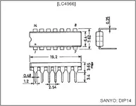
 U109 is an LC4966 quad bilateral switch...a 14-pin chip on the BUSS A PCB. You've got 4 of them on there, each does the monitor switching for each pair of channels (1-2, 3-4, 5-6 and 7-8), so it may be a problem with U109 itself OR the switching that tells U109 when to switch.

This is probably going to be tough and I don't know how tough because I don't have a 388 opened up or accessible in that way right now, but you need to see if you can measure tone voltage at the channel 1 input of U109. That's pin 1 of U109. If you have the manual you can find the picture of the PCB toward the back of the manual where all the PCB layouts are to locate U109, and then once you find pin 1, if you can get your meter probe in there to see if signal is getting to that point. BE CAREFUL. I cannot be held responsible at this point or any point if you do something to hose your gear. Not wanting to pass judgement on your skills but this is getting deeper and you CAN MOST CERTAINLY cause damage to yourself or your gear if you are not careful. Proceed at your own risk because you're going to have to do this with the unit powered and tone going into a channel and routed to PGM group 1 as before, but the space will be cramped at best to get your probe in there.

So, if comfortable, check pin 1 of U109 for tone. Then check pin 2. That's the output of that section of U109.

Then set your meter to DC volts and see if you have any voltage at pin 13 of U109. Pin 13 is where the control signal comes from to tell the switch for "channel 1" of U109 to close and let signal through to the monitor buss, tape track and master meters.

What I'm hoping is that you have voltage at pins 1 and 13 (i.e. signal is GETTING to U109 and control voltage is there TELLING U109 to close), but nothing at pin 2 (i.e nothing comes out the other side because U109 is hosed and that switch isn't closing). If this is the case, this would also mean that you can't hear anything playing back from track 1 either in the monitor section or at the tape out jack.

I'm hoping this is the case because it would just mean that you need to replace U109...unless it got hosed because something else ain't right...but let's hold that thought and check these things out first.
 
Last edited:
Ok it definitely plays tape on track 1. But the meter does not swing at all.
I have to move house tomorrow so opening her will have to wait until sunday.
But thanks for the help.
 
:???: Dang.

Which meter doesn't swing? The master meter or the PGM1 meter, and do you know if that meter (if you are talking about the PGM1 meter) works at all?
 
Okay...yeah, so tell me about the meter, if you mean the TRacm1/PGM1 meter or the master meter, and measure the voltages that I talked about above if you can. If those measurements pass muster then we are on to U113.
 
The PGM 1 meter. Never moved when it should've.
I remember it moving a little if I plugged a mic in and armed it
to all the channels. I don't know what that means though.
 
It mainly means that something's not working...

Measure that stuff if you can.

Let me know if you have any questions.
 
Ok I tried twice to measure the pins on U109. Not easy.
I could not for the life of my mother figure out which pins were which.
I measured voltage on the top and bottom pins on the fader side of the chip
but couldn't get anything on the two on the meter side of the chip.
The top pin measured similar voltage to what was going in but the bottom one measured much more, 32v maybe.

I'll have another crack tomorrow, hopefully with better results.
 
Back in post #172 I linked the datasheet for the LC4966...it has the pin assignment on it.

I put a picture below. DIP style chips (Dual Inline Package meaning two rows of pins) usually have a notch at one end of the chip as well as a dot in the case. The dot usually means pin 1 and the notch is at the pin 1 end of the chip. The pin number assignments go around the chip in a 'U' shape starting with pin 1. Hope that helps.
 

Attachments

  • LC4966.jpg
    LC4966.jpg
    50 KB · Views: 191
Ok I measured voltage at pin 2 and 13 but not pin 1.
I'm going to check again because I'm not sure that's right.

Thanks for the help.
 
Back
Top