SteveM
New member
evm1024 said:....
Or convert eq from NAB (thats IEC1 if I recall correctly) to IEC2.
.
EVM, how exactly would you do that?
evm1024 said:....
Or convert eq from NAB (thats IEC1 if I recall correctly) to IEC2.
.
The 30 series channel cards have a set of links that allow the channel to be switched between NAB and IEC depending on which links are there. Kind of like a jumper, but with soldering. It's in the service manual.SteveM said:EVM, how exactly would you do that?
")
Beck said:The 38 is already IEC/CCIR (European standard). IEC2 is NAB.
jpmorris said:The 30 series channel cards have a set of links that allow the channel to be switched between NAB and IEC depending on which links are there. Kind of like a jumper, but with soldering. It's in the service manual.
Modifying it to 7.5 IPS would be interesting, though - AFAIK the capstan speed control board is attached to the motor itself, but I guess you could swap in a '32 controller and see what happens - or just switch it into 7.5 mode, since it may even be the same board, just without the speed switch...

")
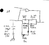
evm1024 said:R104 and C103 form the low freq EQ. In IEC configurations R104 would be 470K ohms (and with C103 at 0.012 uF this gives a low eq freq of 28 Hz which is below the heads low end response and thus appears as a flat EQ. In NAB mode R104 (in essence) becomes 235k so the EQ freq becomes 56 Hz or close enough to 3180 uS for government work. (should be 50 Hz)
Regards
SteveM said:EVM, a little over my head but are you saying the caps and resistors working together create the frequency? Just trying to get a little idea how that works.
yes.SteveM said:caps and resistors working together create the frequency? .
 , but not exactly so
evm1024 said:Steve, do a quick google on RC filter and you will see how RC filters work. Some good write-up but no need to go beyond a photo of the filters curves. RC filters selectivly pass based of freq.
Not sure what yo mean by create the freq but the photos of filter curvs should be yyour answer.
How it works in the tascam EQ....
The caps and resistors form a newtwork of low and hi pass filters which are in the feedback loop of the EQ opamp.
An opamp tries to combine the input signal and the output (of the opamp) so that it equals 0. The feedback network takes the output signal and returns it to the input.
If the feedback network has 0 resistance (actually the same resistance as the input side resistance but I am simplifing) then the opamp has a gain of 1. 1mv in is cancled by 1 mV out.
A low pass or high pass filter has constant resistance (up to or down to respectivly) the filters frequency then an increasing resistance beyond that.
As the resistance (impedence actually) of the filter increases (based on change signal freq) the gain of the opamp increases.
Dr ZEE said:
run away Dr ZEE said:
SteveM said:Actually Mike, good info there.
and I am second to thatevm1024 said:Toss 2 of them together and ....
Toss couple of them and you feel like a "filter master"