F
frnkfrkl
Member
One more thing: J171, pin 3 to chassis ground, resistance measure, MACHINE OFF, NO POWER = 6.0 MOhm. Powered up = .OL. So something is opening that circuit at power-up.
Don’t strap pin 3 J171 to chassis ground…strap it to the power rail’s 0V reference on pin 2.Grounded J171, pin 3 to chassis ground. No change.
I'm still a bit worried about the crackling sound on power-up (well, the no audio problem is also an issue, of course). It seems to correspond to the flickering VUs. Once the machine has stabilised, the lights are at full brightness and the crackling sound stops. It also seems to correspond to what I assume would be the delay time before the relays are supposed to kick in (or out). There must be some correlation between the crackling and strange VU meter behaviour and the non-tripping relays because, if I'm understanding this correctly, they are on the same rail.
I would actually consider 6MOhm open circuit. That is very high resistance and the fact you have something measurable when the system is powered down is likely only because of some stray path to ground when components are not in their powered state. The bottom line is, after a few seconds, there should be a low resistance path to ground measurable at J171 pin 3. Where I remain confused is the fact you manually grounded pin 3 and there was still no change. But something is not right with the +6V supply, and always always always start with the headwaters…the power supply has to be working right before you do anything else. You could also shotgun the two diodes in the timing circuit (D805 & D806? My copy of the schematic is not very good quality). I know you were talking about doing that earlier and I steered you away, but I’m changing my opinion on that a bit. But first we need to sort out the lamp power rail.One more thing: J171, pin 3 to chassis ground, resistance measure, MACHINE OFF, NO POWER = 6.0 MOhm. Powered up = .OL. So something is opening that circuit at power-up.
…Remember, I am NOT a tech. I'll need to read this a few more times to get it to sink in.
did a sort of Kung-Fu transistor swap as well, that is to say I did not completely remove the board. I managed to get just enough room to solder the new one in place. Fun fact, the old one tested fine when out of the machine so that was a waste of time and effort.
I will need to disassemble the machine completely this time. I will need to buy and learn how to use an oscilloscope. I will need to source obsolete parts (actually, maybe not, diodes, caps and resistors should be available). The real hassle is that the machine needs to be reassembled to test what I've done and, if it didn't work, I need to tear it all apart again. This is above my pay grade but I don't have a choice because there's no tech anywhere near where I am.
Could you recommend an oscilloscope? Total noob with one of those. I will read, disassemble, test what I can and advise at that point.
One more question: When testing the power supply itself, is it necessary that it be connected to the things to which it is supplying power? That would seem physically impossible with all the wiring harnesses
There are more things to test besides capacitance. ESR is another. But, look…those caps are over 40 years old. And these are not caps that were manufactured like some of the high-quality computer-grade caps that are found in the power supplies of like my Ampex and 3M machines that are approaching 60 years of age and still test within spec, capacitance and ESR. Those old caps are likely in need of replacement. New caps will bring related performance specs to better than new, the caps aren’t expensive, etc. You should not be groaning about this. You pulled them. Replace them. Market it with that recapped power supply. Its a marketable value-added feature.Well, all the caps are out and, guess what? They all test within spec (+/- 20% or better). Sigh. Everything in here looks OK.
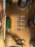
I’m not sure what your numbers mean…590, 240, etc. Depending on the tester, diodes should read a given voltage in the forward direction and zero in the other.One more question that i should probably know the answer to: Can you test diodes in circuit? There are 4 banks of 4 diodes on the PCB. Two of the banks test as one would expect, 590 and zero. The other two banks test 590 and maybe 240 the other direction. Those, however are connected to caps so I'm guessing that they're not testing correctly. I'm really not spotting anything yet on this board that is an obvious glaring fault...
Thanks.Here are a few photos. D801-D804 are discrete. They apparently are used for rectification. I have 4006s here. OK?
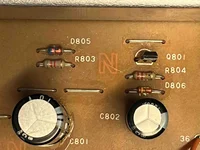
D805 is the same reference. 4006, again?
D806, however, is different. A switching diode, 40V. 4006 ok?
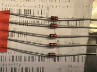
I also have, for whatever reason, several Zener diodes, 10V, 1watt, DO41. I assume that's not what I want for any of these.
All diodes in circuit look physically different than 4006s and look more similar to my Zener diodes. But, never judge a book by its cover, right?
I presume you meant "I WOULDN'T be going hog wild on all your diodes".
Just to get my head on straight. The mute circuit is using the +6V rail as reference, you say. That means relay stuff is just using the rail as a messenger, telling it that the machine is powered up? And when it sees +6V, it "knows" to do what it's supposed to do?
If that's the case, that brings me to the 3 seconds of Rice Krispies/Frying Egg sound and flickering VU meters on power-up. That would be some kind of wonkiness in that +6V rail because it powers the VU meters, right? Which is why I'm getting the sound and light show. And, in turn, if that signal is not "healthy" the relays won't trip.
I know it's not in the VU meter circuit, per se, because, as an experiment, I disconnected the VU meters from the circuit and powered the machine on. No light show, obviously, but the crackling sound was still present which implicates the power supply(?)
In layman's terms, is this the scenario? I'm really just trying to get my head around what I/we am/are trying to fix. Again, I greatly appreciate your time and effort.