Soundtracs MX Story...

  • Thread starter Thread starter sweetbeats
  • Start date Start date
Great job and that's a beautiful mixer. The way those channel cards are mounted (also everything else) is a very underrated aspect of pro consoles. Say what you want about "PRO" but access and service is THE selling point here. I recall many sleepless nights and handful of hairs trying to pull channel cards out of my M-320B mixer. Never gonna do that again but the Soundtracs, seems like a joy ride in this respect. Nice. :)
 
It's just incredible! Amazing job so far! My M3700 is envious of you Soundtracs MX.
 
Thanks for the comments everybody! :)

Daniel, yes, the serviceability is great. Now, keep in mind that once I go through the mixer it is unlikely that I will have even an infrequent need to pull modules out, but its nice to have the feature for when that time comes.

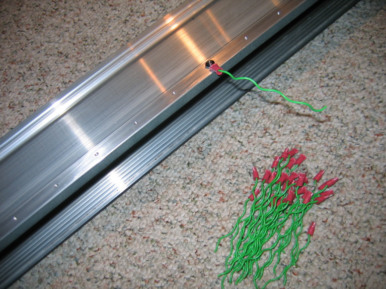
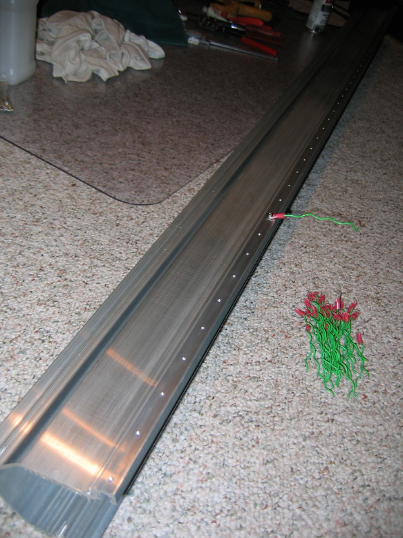
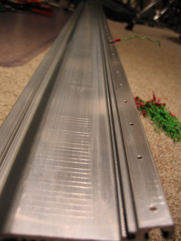
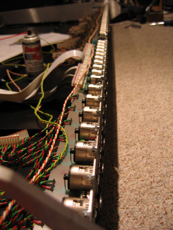
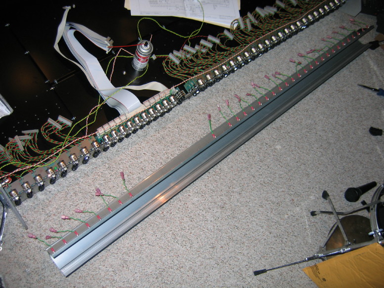
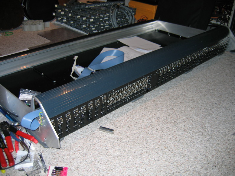
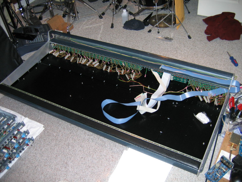
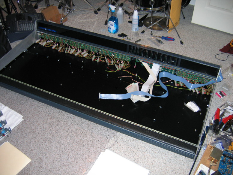
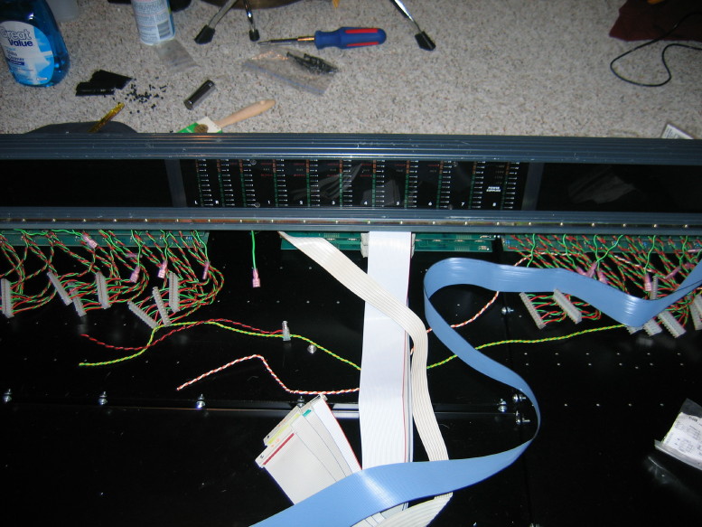
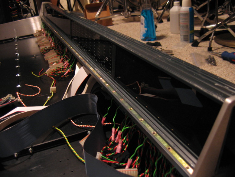
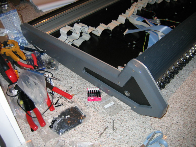
So I got some work done on the meter bridge housing the other night. Just to refresh, what I'm doing to the housing is drilling and tapping holes to fasten ground straps for each module dress panel...that's 42 holes altogether since the frame holds 42 module spaces (32 channels and the master section occupies 10 spaces). The master section only has one strap, but since I'm setting the mixer up to be a different configuration (24 x 2 x 8 x 8) and if I ever changed it back (32 x 2 x 8) OR changed it to a 16 x 2 x 8 x 16, then having a tapped hole for each module space is important...figured I'd do them all at once since I was setup to do it. Came out pretty good. I used a hand drill to drill the holes and cut the threads. I used the threaded rails to which the modules gasten as a guide for marking holes...I offset the rails a 1/2" or so so that the screws coming up from the bottom of the housing wouldn't conflict with the screws from the modules, and then I just used a drill bit in hand to mark the holes through the threaded rail...sort of a poor man's transfer punch. Wpinning the bit in my fingers left enough of a dimple in the aluminum to have a positive placement for my spring-loaded center punch. Here are some pics and you can see the pile of straps that are partially done:

IMG_9877_1_1.JPG


IMG_9879_2_1.JPG


IMG_9881_3_1.JPG


That's one of those jobs I've sort of been dreading so it felt good to get it taken care of.

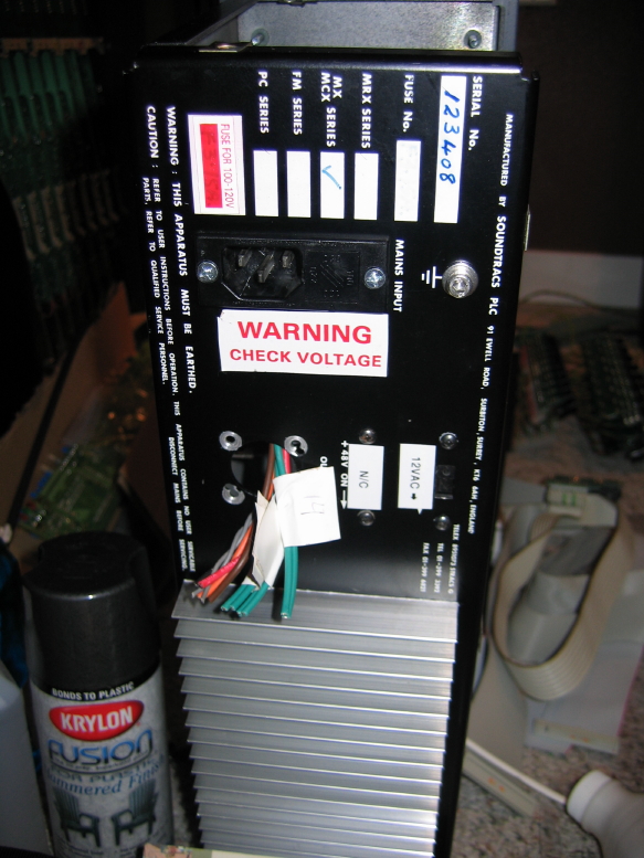
The next job I'm sort of dreading is soldering up the new power interconnect connectors and cable. Did some prep work on that...bared metal on the PSU cahssis and on one o the new chassis-mount connectors in order to ensure positive continuity between the cable shield and the chassis. These spots will get star washers and conductive grease sandwiched between them.

IMG_9883_4_1.JPG


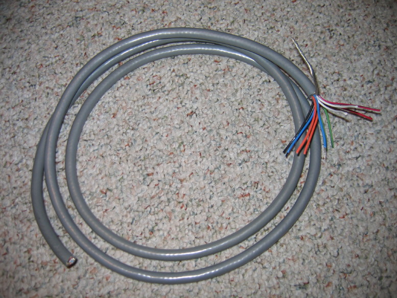
Here's the cable...its Belden 9261...nice quality:

IMG_9884_5_1.JPG


I also started stripping spots on the jack PCB's to solder up the new ground straps for those as well.

Bit by bit...
 
Holy moly Cory! Never saw this thread. Man, you are one brave dude!
 
Holy moly Cory! Never saw this thread. Man, you are one brave dude!

"The line between bravery and utter stupidity is...well...really thin sometimes." ~sweetbeats

Heheh...

Shoot. Those new connectors I got for the power interconnect do not reliably conduct through the connector shells which is key in tying the PSU and mixer chassis together (through the cable shield). I figured out how to get them apart last night (how to get the pin and socket inserts out) so I can soak the drab green painted parts in gasoline or some other solvent to strip the paint off. That will be step 1 to trying to improve the conductivity through the parts of the shells, and there may be some other mods necessary.

I've made more progress on fabbing all the grounding straps from the meter bridge housing to the module chassis panels. I also located a source of the proper end caps to that aluminum rail I'm using for the structural rails on the bottom of the mixer. I even got a couple samples from them so I can get my measurements and start fabbing those parts and getting the last sets of holes drilled in the backplane and bottom panels. Once those holes are drilled then I can finally clean those panels up and start reassembling them. It'll be good to have an assembled frame again.
 
Been getting some stuff accomplished on the MX...

Painting:

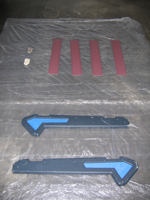
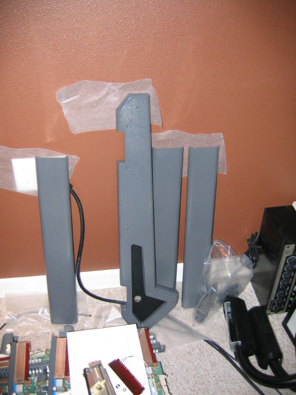
The new aluminum rails that will go across the bottom panels have plastic covers...I got the material for free so I couldn't be picky about the color...the cover material is sort of mauve...so I'm painting them as well as the left and right panels of the mixer (which are pretty scratched/scuffed/gouged up) AND the two bottom rail end caps that I got as free samples. Here are the parts laid out ready for a dark gray that very closely matches the base color of the module chassis dress panels:

IMG_9887_1_3_1.JPG


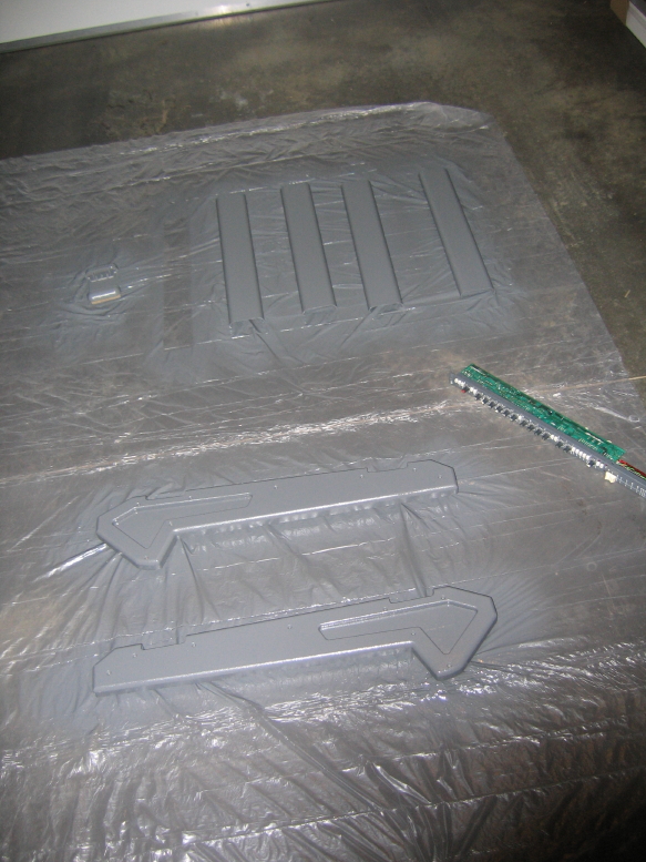
After the first couple coats...you can see an input module sitting to the right...pretty good match for rattle-can paint:

IMG_9892_5_3_1.JPG


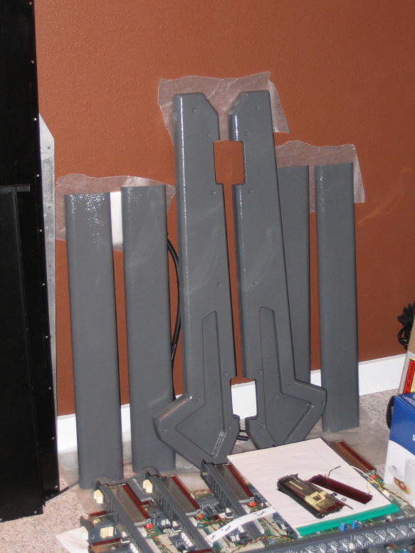
After the final coats, curing in the studio:

IMG_9897_6_3_1.JPG


I got the 6 other end caps today that I tracked down from the manufacturer of the rails. I ordered them in a dark gray color and they are VERY close in color to what I sprayed on the other parts so I'm in luck! I also got some of the aluminum rail material to my machinist friend to cut to the proper lengths. He's got better equipment for making more precise clean cuts. Just waiting for those to come back and then I can drill the holes for the rails to attach to the bottom panels, get everything wiped down and start putting the frame back together. I already spent some time beating on the bottom panels with a block and hammer, and while I haven't got a future as an auto body specialist, I did get the panels straightened out and got many of the dents and creases diminished.


Continued work on the PSU...got the power input jack remounted:

IMG_9889_2_3_1.JPG


I'm at a cross-roads with what to do about the power interconnet connectors...more in the next post.

Mostly finished the straps to tie the module chassis dress panels to the main frame for common grounding:

IMG_9890_3_3_1.JPG


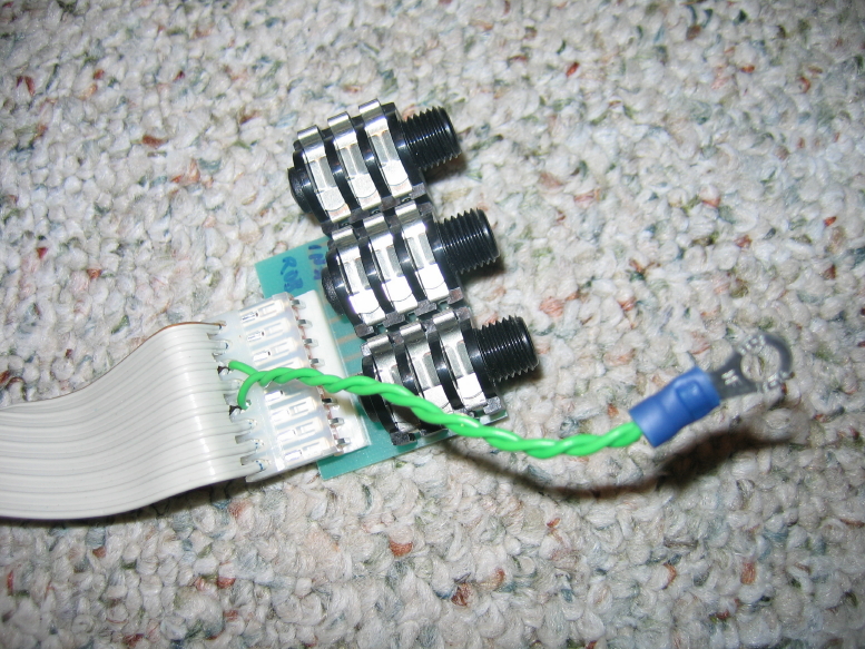
New grounding for the monitor and oscillator out jack PCB...even though these jacks sit RIGHT above main ground lug on the frame the grounding used to go along the 2' long cable to the master section, through the master section and then through 2' of ribbon cable to the master section jack PCB's and then through stranded wire to the chassis ground lug...Go figure. I clipped the wires from the ribbon cable to the connector and punched down new wires that you see below...short, with a ring-connector to go to the ground lug. I also clipped the wires at the other end of the ribbon cable to eliminate essentially a 2' antenna coming off the master section.

IMG_9891_4_3_1.JPG


I have also finished baring spots on all the jack PCB's for new ground straps from each PCB to the chassis, and most are drilled for the ground wire. Just need to tin them and solder up the wires. I'm also going to apply Tarn-X to all the XLR jack pins and make sure all the wires are securely punched down to the connectors that plug into the channels strips with the wires from the jack PCB's.

Biggest conundrum is what to do about the power interconnect connectors...
 
So here's where I need some advice/input...

If you've been following along you know that my intention is to replace the stock connectors and cable that interface the mixer with the PSU, and this is because I ideally need 12 conductors to properly run the 0V connections, and I need for the cable to be shielded and therefore metal connectors to propogate that shield which is also the common connection for the PSU and mixer chassis. The stock connectors are plastic and the panel-mount connectors are only populated with 8 of the 12 possible pins...don't know the make of the connectors so I can't easily find new sockets and pins...can't determine what tool to get or how to extract the pins to retrofit into a new housing, the current cable isn't shielded, etc. So that's what led me to get the new mil-spec style connectors featured in post #60...

But I ran into a problem...getting continuity through the pieces of the connector (for the chassis-to-chassis ground connection) was entirely unreliable due to the tacky olive-green paint, and also somewhat due to the construction...these aren't genuine mil-spec connectors after all...I got them because they were relatively affordable, okay? they cost me about $25 shipped for the two sets. So I thought "no sweat"...I'll just strip off the paint.

Before I could do that I had to figure out how to get them apart which I did. It wasn't easy. They weren't really designed to easily come apart and I had to mod one of the shells to do it because it wasn't like its counterpart. Tacky. So I got them all apart, all the while becoming less and less enamoured with my cost-saving efforts and more and more astute to why they were $25 for the two sets.

Stripping the paint off was a royal PITA. I tried solvents, no go...So then I tried a baking soda stripping technique I read online which should have taken 15~20 minutes and took 3 days and STILL didn't really strip them. I used some other cleaner and multiple brushings and they still look sort of nasty and then I realize that it is really just low-grade aluminum, not a more appropriate alloy. The paint was maybe lead-based...I don't know...I was able to polish one up a bit with a mini wire brush on a Dremel type rotary tool but it is also taking base material with it...lotsa work for a so-so result on a poor-quality product.

Textbook woulda-coulda-shoulda.

It was originally recommended to me to get a set of these from Mouser which would run about $78 plus S&H, but are leagues beyond in quality compared to what I got and wouldn't have the continuity problem.

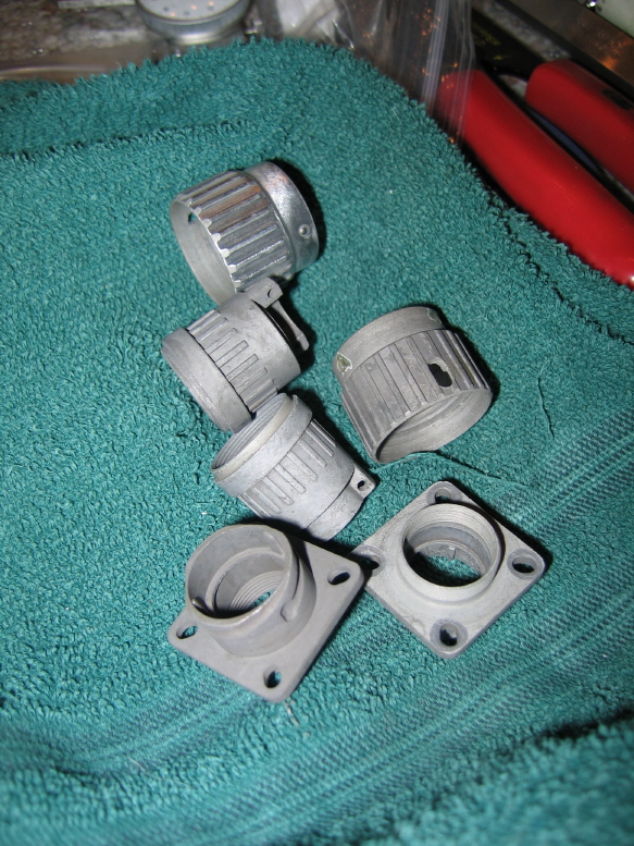
Here's what the housing parts look like today:

IMG_9898_7_3_1.JPG


So what do I do? Get the right thing or keep messing with the ones I've got? I'm still not sure if my continuity problem is resolved with the hours I've put into the ones I have...and at best they're ugly and maybe work, which maybe I can mentally deal with, but the quality is not up to par with the rest of the mixer. That may or may not be any kind of operational issue. At worst they are ugly and I have to come up with another plan for how to get the ground continuity reliably through them...and who knows about the material and spec of the pins in them. I know they are gold plated but I'm pretty sure the base material is low quality as with the insulator block...curious to see what happens to that when I start heating things up with the soldering iron. Ugh! Stupid!
 
You already know the answer.

With so much effort already poured into this board I can't imagine you really using those connectors.

Get the good ones. You'll never have to worry about it again. If you keep the low quality ones just after you've forgotten all the steps you took to replace the originals the cheap ones will fail and you'll have to do it again...
 
Hmmm...Yeah...maybe I already know the answer, but I'm a cheapskate.

I put one of the sets together and I get good reliable continuity through the shell of the whole set...so then I'm thinking "maybe this will work." Then I get the bright idea that maybe I can clarify the appearance with some heating from a propane torch. Unh-unh...this metal is the aluminum equivalent of pot metal...within a short time of the application of the torch the stuff was distorting and starting to melt...total cheese...

Ugh...$80...

"As a dog goes back to its vomit, so a fool repeats his stupidity."
 
Acts as a functioning replacement: Check
Does the job even better after some mods, if needed: Check
Is shiny:............

Nope. Looks like it didn't pass the Cory test. :-)

Hmmm...Yeah...maybe I already know the answer, but I'm a cheapskate.

I put one of the sets together and I get good reliable continuity through the shell of the whole set...so then I'm thinking "maybe this will work." Then I get the bright idea that maybe I can clarify the appearance with some heating from a propane torch. Unh-unh...this metal is the aluminum equivalent of pot metal...within a short time of the application of the torch the stuff was distorting and starting to melt...total cheese...

Ugh...$80...

"As a dog goes back to its vomit, so a fool repeats his stupidity."
 
Heheh...that's funny.

True too I suppose, but its not just about shiney...I couldn't believe how quickly the metal started melting before my eyes under the torch. Maybe I can use them for something else later, but the power connector and cable have to at least match in quality to the rest of the mixer...I mean, the power umbilical...its like the aorta...not a good idea to use cheap parts. Functional? Yeah...basically...which is why I'm grappling with this because I don't like spending money and I think they'd work...and its not like its going to get plugged and unplugged on the road...its going to get plugged in and stay that way...maybe always.

Urg...

....................?
 
Well...long as you're not keeping the console next to any blow torches? :D


Just thinking out loud here, but what about hard wiring the umbilical to the console?
 
That is indeed a thought...Or even hard-wire one end and save half the cost of the connectors. I think there are good arguments for having at least one end on a connector.

Hm...have to think about that.

In the meantime I'm getting the frame back together. I get the cut aluminum rails back tomorrow for the bottom, and since the bottom panels and end panels need to be assembled in order to place, drill and fasten the bottom rails I thought I'd better get those things together.

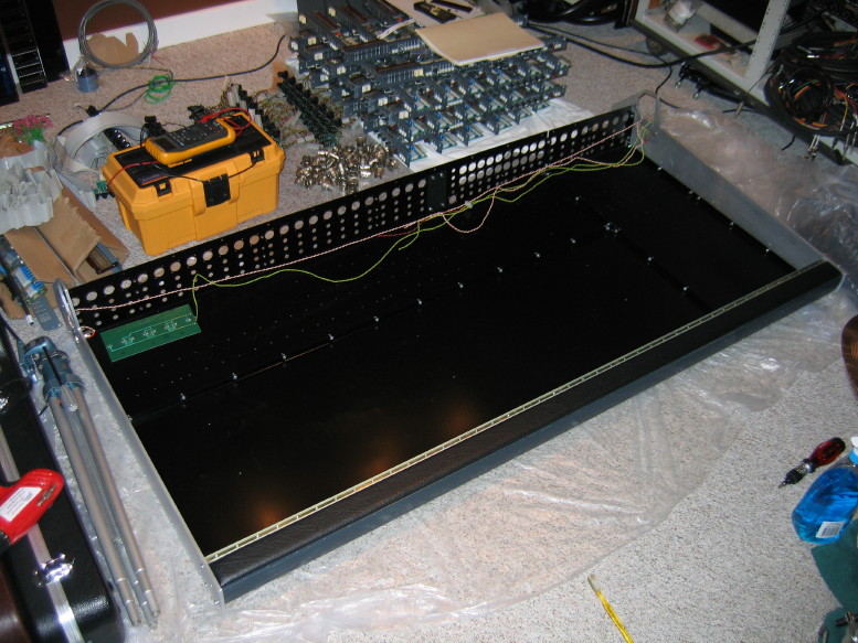
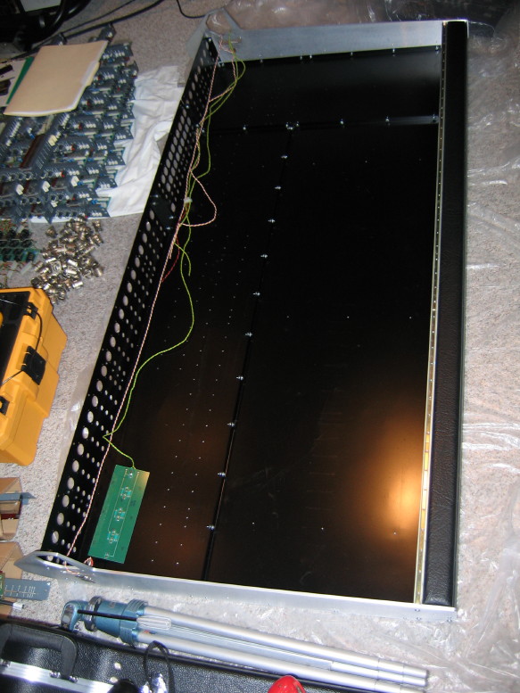
Backplane/bottom panels, end panels and armrest assembly all put back together with threaded fasteners instead of the stock rivets...I get great continuity between all sections and after beatin' on stuff the bottom panels fit together with far less tweakage than before:

IMG_0017_4_1.JPG


IMG_0019_5_1.JPG


A view from the underside:

IMG_0014_1_1.JPG


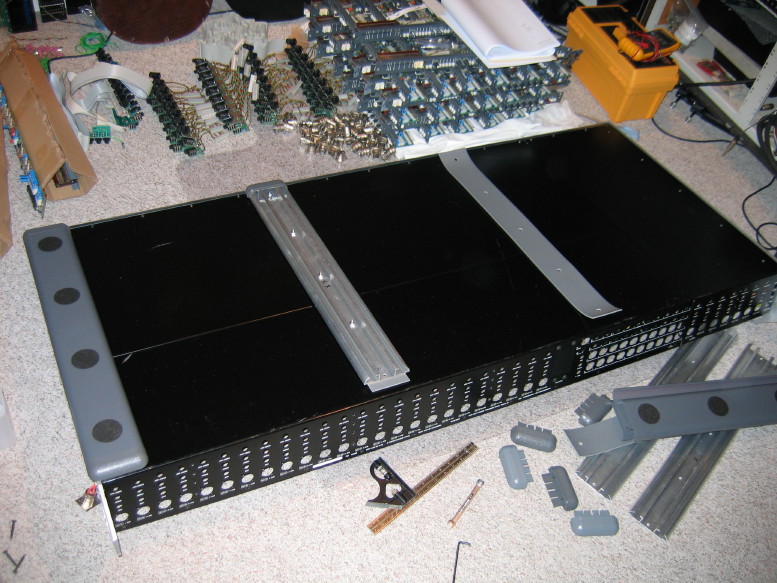
Probably hard to tell but the bottom panels didn't form a flat plane before being sort of caved in...they do now. Also you may have noticed sort of a mock-up of one of the future bottom rails and its potential placement relative to the end panel...pretty good for found parts, and BTW the end caps on the bottom rail are the ones I purchased and have not been painted to match, and yet are a pretty good match! Here is a little closer view:

IMG_0015_2_1.JPG


And another shot of one of the end panels since I took the masking tape off to reveal the black inset section:

IMG_0016_3_1.JPG
 
Just need to pick up some more #10 washers and the structural mods will be done (i.e. the new bottom panel rails).

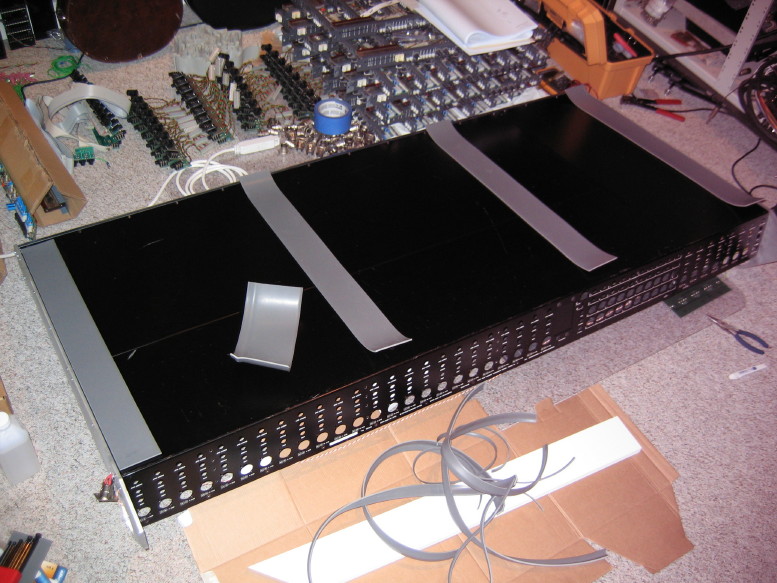
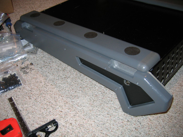
The right and left aluminum end panels actually stick out about 1/8" more than the bottom panels. I had originally remembered they were flush but when I got it back together I was reminded they are not. I bought a scrap of grey rubber cove base and trimmed pieces to go between the rails and the bottom panels...here are the four pieces cut and ready:

IMG_0036_2_1.JPG


And at long last, after the aluminum rail was cut, cleaned, drilled, and the plastic covers cut, painted and adorned with no-skid pads, and the end caps acquired, and the bottom panels drilled, and the above mentioned spacer material acquired and cut to size, I am finally putting it all together. This picture shows the progression of the assembly with the far left rail completely installed, and backwards progression as you move to the right:

IMG_0037_3_1.JPG


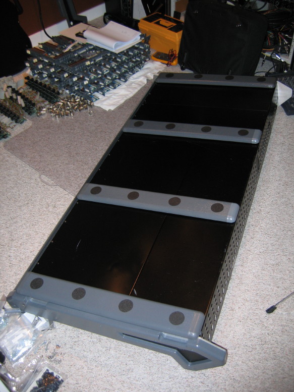
Okay...so for all of you asking "why did you go to all that trouble?", the original design basically ensured that the bottom panels would cave in upwards risking damage to the ribbon cables and potentially the PCB's as well, and the risk was verified for me by the fact that there WAS damage to a couple of the ribbon cables. There is no room inside to beef up the structure, so in essence the solution here is to add an exoskeleton of sorts. I like stuff to look like it "belongs" and when I found the scrap aluminum rail and plastic cover I thought "that would work", and here we are.

I can tell you, with where I'm at in the assembly process, the new rails greatly enhance the rigidity of the bottom panels. They will provide good protection.
 
Done!!

Structural mods are done. Phew!

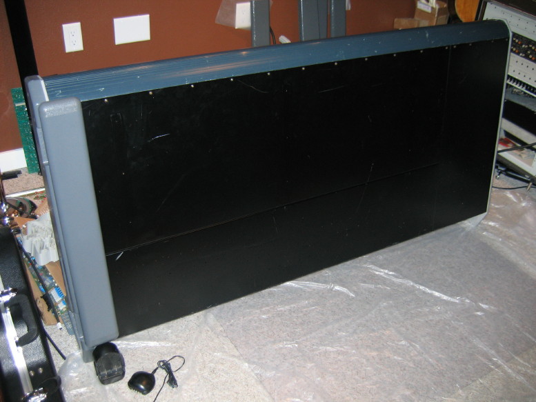
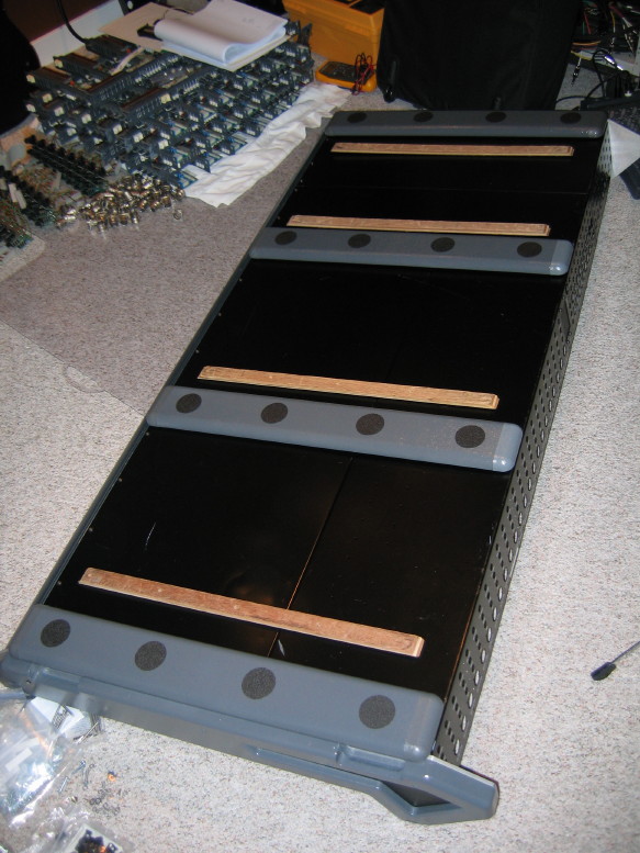
Here is what the underbelly of the beast looks like now:

IMG_0004_2_1.JPG


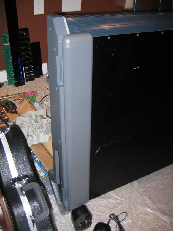
Here is a closeup if the side detail with the side panel temporarily held in place (can't permanently install those until the meter bridge is installed):

IMG_0002_1_1.JPG


And just for fun here are the original plywood skid strips sitting side-by-side with the new rails. That's really all they were was sacrificial rub strips, but the problem is that because they were mounted relatively inboard from the side panels as well as the front and back of the mixer, and because they DID protrude height-wise beyond the end panels (which, by my estimation, can and should carry the weight of the mixer), it was a sure-fire recipe for caving in the bottom panels, and they were indeed deformed. Now the outboard rails are really going to be doing the bulk of the support work since they sit under the end panels, and the inboard rails are there for additional structural integrity to the bottom panels and certainly offer some support to the transverse structural members. Heheh...looking at this picture, you can see that even the WOOD has been tweaked (following the shape of the formerly caved in bottom panels)...looking particularly at the one furthest away you can see it is bowed compared to the furthest rail assembly:

IMG_0005_3_1.JPG


I have already flipped the frame assembly onto its new "feet" and have already started soldering up the new ground leads to the jack PCB's. Once those are soldered up then I can start remounting jack PCB's and XLR jack shells, and then the meter bridge can be reinstalled.

SWEET!
 
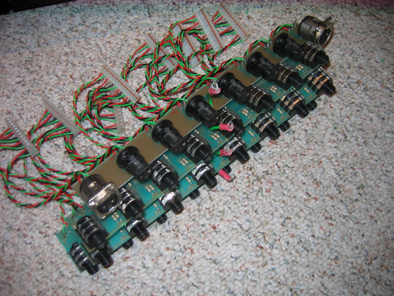
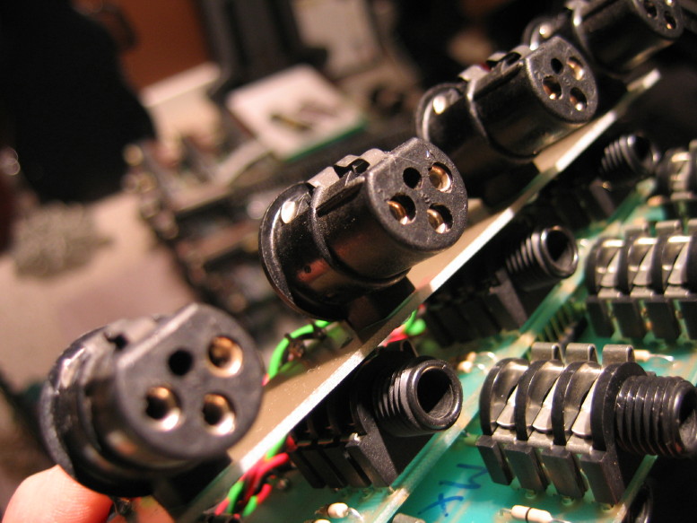
I got all the jack PCB sets up to snuff...that includes modding for a new ground lead, cleaning out the TS/TSR jacks, deoxidizing the silver contacts in the XLR jacks, and re-punching the wiring in the connectors that mate with the PCB's to make sure there is good contact there. That covers all 136 jacks which are contained in 5 jack PCB sets (4 input sets and one master set).

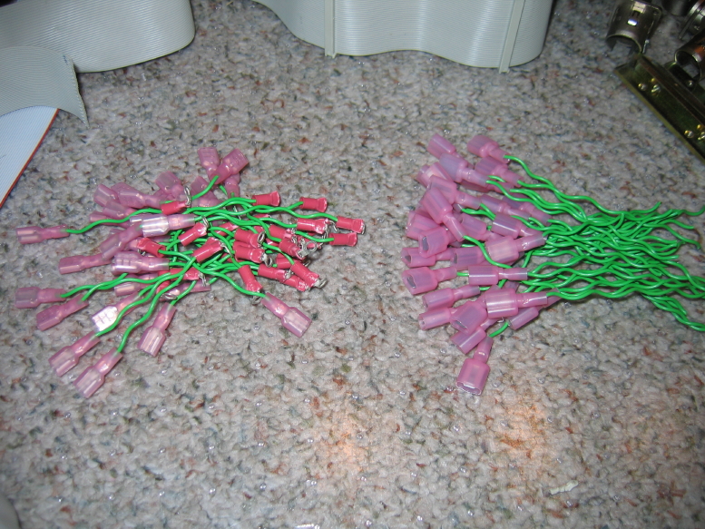
Here is one of the input sets. You can see the new little grounding pigtails coming out of the center of each PCB...the green wire with the pink crimp ring terminal. The wire is recycled from the power supply mods. Its good wire and there was enough for all the tails on all the PCB's:

IMG_0006_1_1.JPG


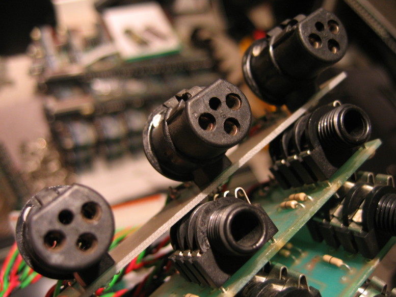
Check out the before and after on the cleaning of the XLR jack contacts...I used Tarn-X and a pipe cleaner, then rinsed with water and set to dry in front of a little heater...

BEFORE:

IMG_0014_4_1.JPG


AFTER:

IMG_0010_3_1.JPG


Started getting the jacks reloaded last night.

You can see one of the new grounds lead in the middle of the XLR jack PCB going to the backplane in the first pic, and then you can see the 4 screws running down the center of the jack sets which creates the ground lug for each of the 4 jack PCB's in the set. Lookin' shiny!

IMG_0018_8_1.JPG


IMG_0019_9_1.JPG


Once the jacks are all back in then the meter bridge goes on and the side panels can be mounted. At that point the frame will be ALMOST complete...just need to get the pins for the connector and wire up the power interface.

I also made up the new ribbon cable for the meter bridge (old was damaged and the new needed to be longer with the move of the 8 input strips to the right of the master section).

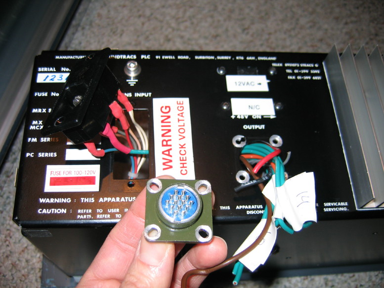
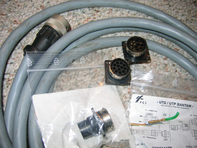
Here's a plot twist on the power connector interface...So I was just about to drop $80 on a new set of Hirose JC/JRC connectors, make up a new cable, etc. etc. Again, this is all because I need at least 12 conductors passing through the interface to handle the new ground-scheme, and, not knowing who makes the stock connectors and not being able to de-pin them and also being stuck with the stock panel-mount connectors short-loaded with only 8 of 12 pins (and not knowing what brand/model pin goes IN there) I was bent on just starting over with the interface cable and connectors. Well, I was in the boneyard at my favorite local electronics shop and sitting there were TWO BOXES of the IDENTICAL panel mount connectors to what is on my mixer in stock trim. Each connector in its own little baggie with all the model number info and a type reference for the pins. I paid $2 for a set of the male and female panel mount connectors, and with new info in hand was able to find the proper pins and sockets for the connectors at Mouser! In the end it will cost about $17 total for the connectors and pins and sockets, but I don't have to make a new interface cable. ;) There is really nothing wrong with the stock cable. The connectors, though they utilize some plastic, work well and are quality parts. The ONLY drawback to the is that the cable is not shielded and since plastic is utilized there is no way for the ground reference from the PSU chassis to propogate to the mixer frame over a cable shield and through the connectors. The overall cable shield is an added protection against environmental
EMI/RFI. At this point it is worth it to me to take the risk of running the chassis-chassis ground through the cable rather than an overall cable shield in order to save time and money...each PCB has local power filtration. If it turns out to be a problem I can always deal with it later.

Here are the new connectors with the stock cable and one of the old panel-mount connectors:

IMG_0016_6_1.JPG
 
Hey thanks, Muck! :)

Got all the jacks in last night:

IMG_0023_2_1.JPG


IMG_0024_3_1.JPG


And got all the individual module chassis ground leads fastened to the meter bridge:

IMG_0027_5_1.JPG


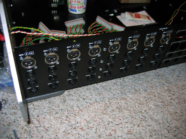
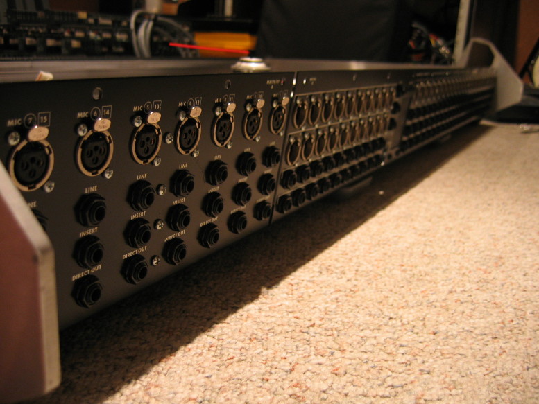
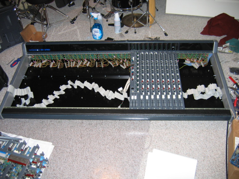
And got the meter bridge housing bolted up...note the jack configuration with the 8 input jack sets to the left of the master jacks...I betcha this is the only split Soundtracs MX in the world..."they" said "I'm not sure if its possible." It is.

IMG_0029_7_1.JPG


Note the new lengthy blue ribbon cable for the meters...this replaces the damaged one and will allow to move the meters even further to the left if I decide to reconfigure the modules into a 16 x 8 x 16 setup...the jacks would stay where they are but the modules would move and the meters would follow the master section to the middle:

IMG_0030_8_1.JPG


Annnd I also got the meter panels installed...remember, the panel used to be one piece with the actual meters all the way to the right where the master section used to be. I hacked it and fabbed little trim pieces to join the now 3-piece meter panel. Came out good I think:

IMG_0031_9_1.JPG


IMG_0032_10_1.JPG


IMG_0033_11_1.JPG


Annnnnnnnd I got the end panels installed as well...just for fun I set the refurbished master section in place for the pic:

IMG_0035_13_1.JPG


IMG_0036_14_1.JPG


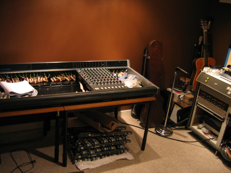
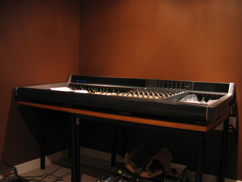
Next step: get the table moved into the studio and get this sucker upon it...need to make room to get my 388 in and get it cal'ed and biased for sale...and tear down the parts machine.
 
The Soundtracs mixer is finally on its permanent perch!

IMG_0127_1_1.JPG


IMG_0128_2_1.JPG


Got the power interconnect pins on the way from Mouser as well as some XR7 ceramic caps for power rail bypass both in the PSU and locally on the cards in the mixer. Once those parts get here I'll be able to finish up the PSU and get the power hooked up...then it'll be on to going through the input modules, getting them cleaned up.
 
Back
Top