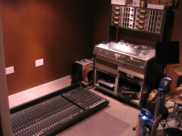
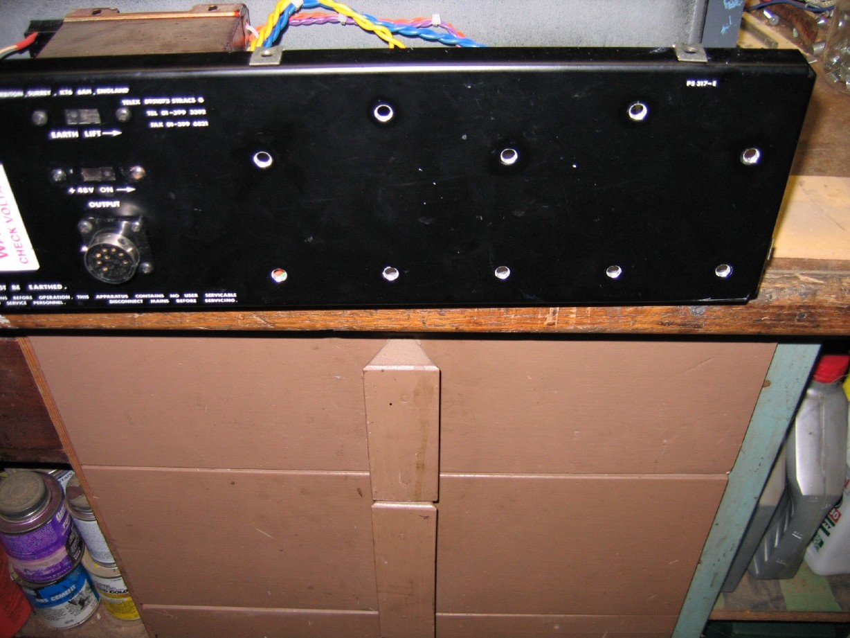
Ah, so that's where the soundtracs is!

All looks amazing Cory! Plan for the cleanup of the mixer sound real good! We're 90% done!! Yey!!
Welllll...not so fast.
A number of things have transpired here...nothing earth shattering but it will involve a little time if I want to have this done right and never have to pull it apart like this again:
And actually the meter bridge has been removed since that picture was taken.
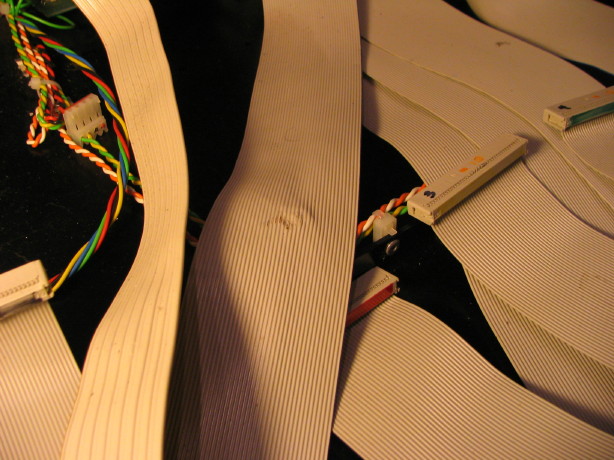
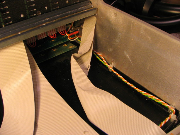
There are two main issues going on...the lesser issue is that the bottom panels have been distorted due to improper placement either during storage, transport or use...I knew this all along as it is easy to see where they are dented and pushed in when you tip the mixer up, but being able to have a good look things with all the modules out I can see that the cabling is getting pinched at certain points...there's no longer any clearance in between the bottom panels in sections and the input channel and group channel cards. This has damaged a couple of the cable sections, one for the meter bridge and one that goes from the jack panel to the master section. One cable is definitely bad and may be the cause of noise in the system from the meters when the oscillator is engaged...see here right in the middle of this picture you can see the tear in the ribbon cable:
Here is the other one...a spot where the ribbon cable was smashed. This cable may still be good as the insulation is still intact...I'm going to test continuity on this one and if it is still good I'm going to use it for the meter bridge cable just in case any strands have been compromised...I don't want to use it for carrying audio signal. The area in question is also right in the middle of the following picture...the darkened distorted area in the middle of the ribbon cable:
I need help...does anybody have any of that ribbon cabling laying around? I can't find that in short lengths anywhere. It is the same stuff used for IDE drive connections in personal computers (1.0mm pitch 40-conductor 28AWG stranded cable)...seems I can get 100' if I want no problem but I only need 2'.
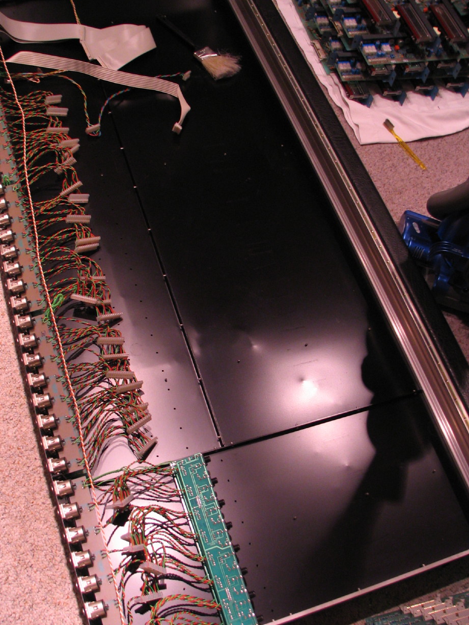
Anyway, that's one issue that needs to be resolved and once I'm done cleaning the meter bridge and can bolt that back up then I can get some wood blocking under the bottom panels in strategic locations and then push things back closer to their original positions to restore the clearance by standing in spots and hopping a bit. It'll never be "straight" because of some creasing and stretching of the metal from the damage...you just can't really ever get rid of that but I can at least restore the clearance and that's good enough for me. You can see some of that creasing and denting in this picture...you can't really see the overall bowing up of the panels in the center but just trust me its there:
So that's the easy issue. The more challenging issue is with grounding. I knew this was going to be something with which to contend as soon as I read "star-grounding" in the manual. I've had the good fortune of reading a 1995 AES publication regarding grounding in audio systems written by AES member Neil Muncy. Neil has made significant contributions to the audio industry and the AES. So a lot of the publication is over my head but it is written in a way such that a lay-person can get the important nuggets and at
least be armed with enough info to start looking at his/her systems and potentially addressing noise issues that are grounding related. The bottom line is that the audio industry has been at odds/disagreement over what consititutes proper grounding, and this leads to inconsistent treatment of grounding and when systems aren't compatible in the methodology used the door is open for problems...problems that even the "silver bullet" of balanced audio cannot fix. I see three main facets to this issue: 1. ensuring that each signal "ground" only has one path to a common system ground reference, 2. that those paths are as short as possible with respect to the point where the signal enters or leaves the system, and 3. that care is taken to how signal conductors are routed and to keep them as far as reasonably possible from higher voltage pathways and particularly unregulated paths.
Here's a practical application: a mic input jack on your mixer; if the common ground reference for audio systems in the mixer is the chassis to which the jack is mounted, then pin 1 of that mic jack should ideally be bonded to the chassis
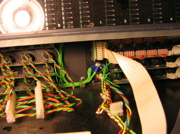
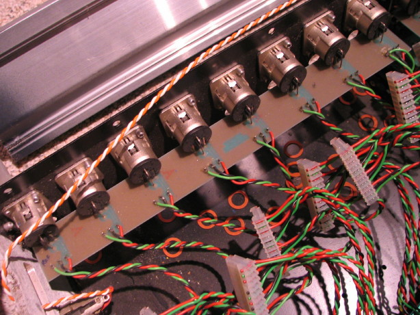
right there where that jack is mounted, where that signal enters the system. My mixer, and plenty others are not...in the case of my mic jacks, jacks are mounted to jack PCB's in groups of 8, and pin 1 from each jack is common on the PCB and then one wire from each ground trace on the PCB goes to a single ground lug down behind the master section...see here in the middle of the pic:
That means that, for channels 1~8, the ground wire for those mic jacks stretches several
feet. So that is a breach of the best practice of having the pin 1 to chassis ground reference connection being as short as possible. That length of wire, in spite of the shielding properties of the metal chassis, can STILL pick up EMI and even RFI, not to mention it is open to picking up internal interference. Remember the other issue with facet #1? That each pin 1 conductor only have
ONE path to the chassis so that no ground loop exists? Well, the Neutrik XLR jacks on my mixer have variable conductivity between pin 1 and the shell of the jack, and the jacks are riveted to the chassis, and there is variable conductivity there as well. I measured resistances in the mega-ohm range (not so concerning but it IS indicative of the existence of
some secondary path) down to 17.5ohms...so does that make sense? Pin 1 of each mic jack goes to its jack PCB which has a common path via the PCB trace to a wire to the star-ground lug, and each jack
ALSO as a path to the chassis through the shell of the jack and its mounting to the chassis. So we've got long ground runs AND secondary paths. Here is a pic of an XLR jack PCB...you can see the lighter brown areas on the PCB are the traces on the other side, the largest of which are the ground traces...the black/red/green wires coming off the PCB are the signal wires from each jack that go to the respective channel card, and then at the top right of the pic you can see a terminal with TWO green wires coming off of it...that second wire is the one fro that jack PCB that heads on down to the star-ground lug:
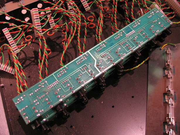
The other jack PCB's for each set of 8 channels are a whole 'nuther story (line in, insert and direct out)...the jack bodies themselves are plastic, so no secondary path to the chassis there, but there is still the same problem of the lengthy common wire to the star-ground lug...and there is a whole additional layer of issues unique to each PCB. The three boards themselves are the same part, but each one is a slightly different assembly as there are components mounted to some as well as a multipin connector because on some M-series models (namely the MRX) there is an integrated patchbay "sidecar" in the frame which interfaces the I/O jacks at the jack PCB...so it isn't a simple matter of isoating the grounds and tying them back to the chassis at the jack...here is a shot of the trace side of one of the jack PCB's:
Let me just recess for a moment to mention that I'm tickled to be getting consultation on this from Neil Muncy himself. There are some seriously nice folks in the audio world. Neil and I have been able to become somewhat acquainted over on the recordist.com Ampex List and we began dialoging about audio system grounding back when I was having grounding issues with my Ampex MM-1000. He's taken time to help educate me and I contacted him with an "Ah-HAH!" when I opened up the Soundtracs mixer and found what I found.
We've now identified that there is potentially a tertiary system issue with how grounding of the modules takes place because there are two grounds carried on that big snakey ribbon cable that interconnects all the cards. So I'm going to take some time with the schematics and the hardware tonight and isolate what travels where as far as grounding, make sure the chassis ground reference is formidable at the point that the power umbilical connects to the backplane and then listen, listen, listen to Neil as we chip away at these issues one by one.
WHY go to all this trouble?
HOW could it be done so improperly in the first place? The M-series mixer design dates back to 1982...the audio world is STILL at some odds about audio system grounding even today...it was VERY much an issue in 1982, and EMI/RFI was also not as large an evil and even lesser so in Europe where the Soundtracs mixers were designed and built. Today? With cell phones and other digital transmissions? Data conduits? Its a noisy world we live in. Plus I can see the radio station that's down the street from the studio windows. Lastly and probably the greatest contributing factor to why I'm doing this is that its me...I can't help myself. I have it opened up. I want to do it right, do it once. I don't want to have it opened up again to deal with noise issues and since the mixer is THE HUB for audio in the studio I want to know I have done everything reasonably necessary to limit noise infiltration into the system and to be able to work backwards from the mixer with any issues as they occur...to have a reference standard to which everything connects.
So I'll post updates to this issue as we chip away at it.
Here is a video I captured a couple days ago after I had everything opened up and the lights started flickering on in my head of just how extensive the issue is...the "What were they thinking" at the end is genuine...that was a genuine "waaiiiit a minute...THAT'S not good..." moment:
YouTube
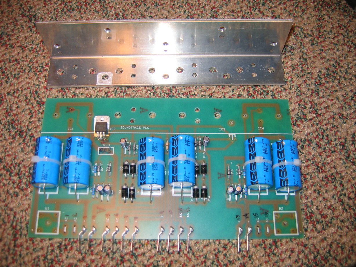
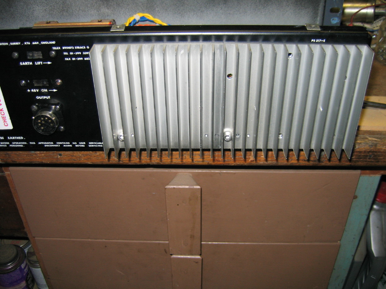
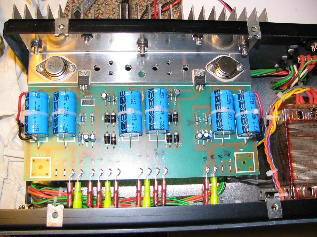
Aside from all this grounding stuff I'm enjoying getting familiar with the guts of this thing, and though I have encountered the previously discussed areas of improvement with the power supply, and now these grounding issues, my strong sense is that this is a great mixer...high quality components were used throughout...the PCB layouts are elegant and demonstrate clear attention to good design, and I still really like the feature set. I am really pleased with the build quality. And I'm also just enjoying this type of design; the single channel modular design...the ribbon cable connections are quick-release latching type and the I/O connectors are low-friction type as well so the modules are super fast and easy to remove. I think it took me maybe 25 minutes to unload the entire frame? I don't want anybody thinking that it is a dud or that I regret getting into it. Like I said before you'll find grounding issues in lots of stuff...I'm simply going to be applying what has come along since it was designed.
Some more pictures in no particular order...
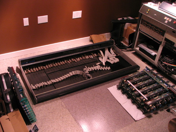
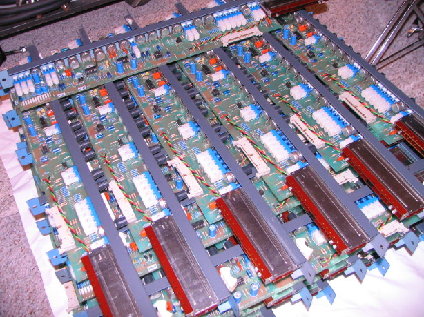
Pile -o- channel strips:
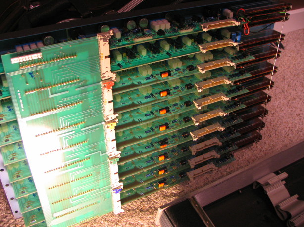
Pretty master section...love those glass fiber PCB's that let the light glow through:
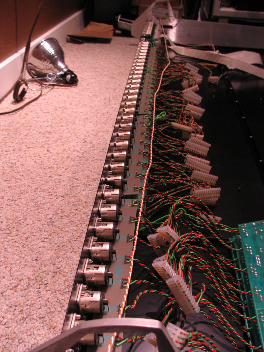
Mommy, lookit all the jacks!
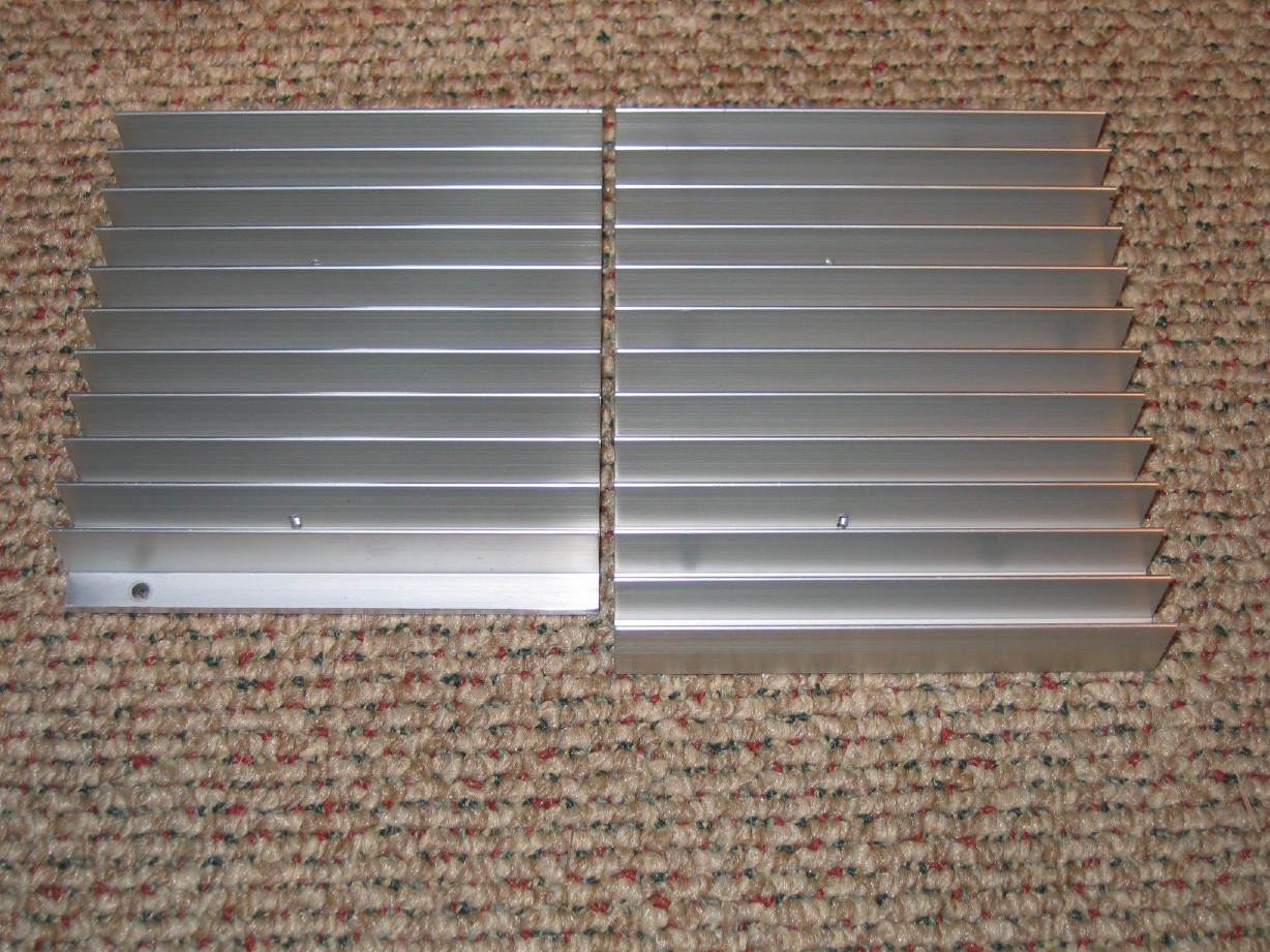
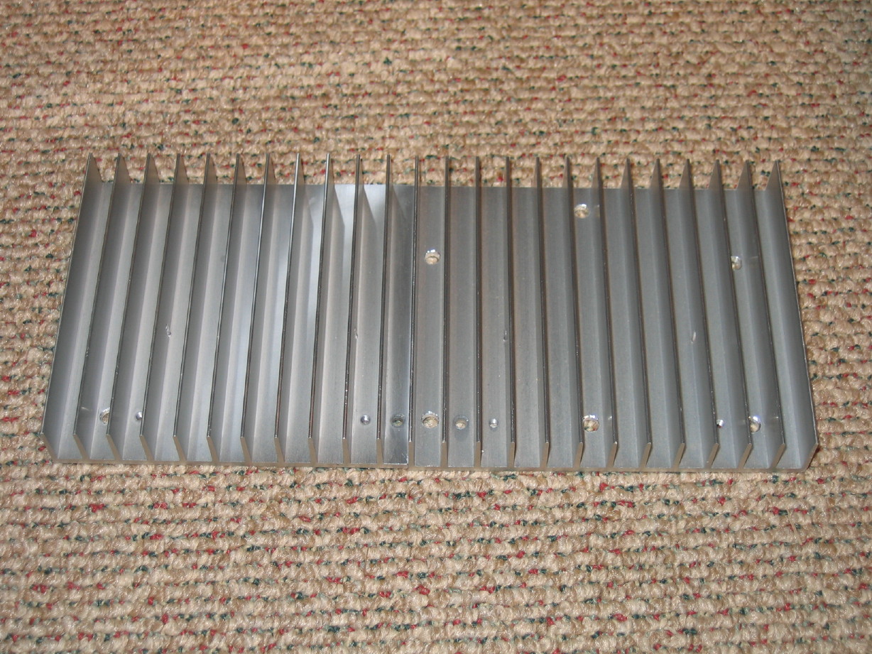
The aluminum extrusions for the meter bridge as well as the armrest are REALLY substantial and quite intricate, and another thing I wanted to show you all from a design aspect is that the threaded holes to which the modules attach as well as the bottom panels and backplane are actually heavy-guage yellow zinc-plated steel inserts. For one thing it would be relatively tough to strip one of these out but if you DID it would be simple to replace that section...I've seen lots of mixers where the strips fasten right to the extrusion or a formed steel panel which is fine but in the field you can only fasten and unfasten those joints so many times before the threads become compromised...eventually they will fail. Now in most cases I wouldn't think it would ever be a problem unless the mixer WAS a dud and you were having to constantly take stuff in and out, but it is simply a better design; better engineering, and it DOES make a difference in the overall rigidity of the frame because you CAN apply more torque to the fasteners between the extrusions and the backplane and bottom panels than would be comfortable without the insert design:

Trying not to rabbit-trail. Very anxious to have this thing up on the table and connected up, but I've come this far and done so much work with the room and the Ampex tape deck that I can't compromise what I know with what I do. Hopefully I can get to the bottom of this grounding thing in reasonably short order and finish getting the frame cleaned up.
BTW, overall the condition of the mixer is good...dusty but otherwise clean inside...NO corrosion at all anywhere.
 when it gets cleaned up, but all in good time.
")
")


 :rolleyes:")