Soundtracs MX Story...

Unfreakingbelievable Cory. I got nervous just pulling a belly pan on my M3700, to remove the wrist pad assembly so the mixer would fit in my console.

Hey Cory, you might be interested in something I learned recently.

From the "for what it's worth" department.......:D

I'm just finishing up my own little mod nightmare. I've been modding my computer enclosure for two new computers that I'm building. And part of the mod, is the computer cases themself as they needed to interface with the enclosure in a certain way so the cooling strategy I've chosen would work correctly.

Part of the computer case mod, required removal of the existing plastic bezel, and fabrication of a new bezel, made from aluminum extrusions from a company called Stylmark. Stylmark manufactures aluminum extrusions in a thousand profiles, and over 500 finishes. I used to work in a Store fixture manufacturing company, who routinely used these extrusions to manufacture all kinds of displays, showcases etc. Over the years, I collected many cutoffs and many full 10' sections.

The case mod required a flat faced bezel to interface the interior front of the enclosure, as the cases are on reversed drawer guides, which means the cases are like reversed rackmount computers, that pull out the back of the enclosure for maintenance. When they are pushed in, the new bezel must come up against a foam weatherstrip seal on the interior face of the enclosure front. On the outside, there is a hinged smoked plex door that also closes against another weatherstrip seal.

Alright, so the problem was how and what to use to fabricate this new bezel. After working all the details out in Sketchup, I settled on a simple 1"x1" channel, which had to be fashioned in such way as it would also frame the modded HD cage and HD adaptors. I did this so I could simply replace HD's from the front, and also allow the HD's to be mounted horizontally instead of vertically. This came about because the cases I chose, were actually Thermaltake Mid towers, rotated horizontally. What a pita. Anyway, so after getting all the details worked out, and the HD cage mounted, now I could fabricate kind of a "face frame" out of the channel.

However, the problem of fastening the ends of the vertical "stiles" to the horizontal "rails". While tinkering around with various possible fastening schemes, and looking through all my extrusions(I have tons of them), I came across another channel that was a very odd size. It was 7/8" wide with 15/16" "flanges".

Wow, it fit perfectly inside the finish bezel channels. All of a sudden, it dawned on me. Not only could I use these to form the ends to make a "butt joint", but I could also use them as a cleat on the front of the computer case for the completed bezel to align and fasten to. Ok, once I fabricated all the little pieces, now it came time to figure out how to fasten them all together. Well, after thinking about it, rivits and screws were ruled out due to various access and clearance problems.

It just so happens, as I was going through this, during one of my daily net search's on welding, I accidently came across a site that was discussing the fabrication of aluminum aircraft parts using adhesives. What they were discussing was the various tests done with different types of "superglues". WOW...ok, it dawned on me. SUPERGLUE! Cool. Perfect......almost.(sigh)

Well, I decided, to get the faceframe all aligned perfectly, I'd have to build a jig to hold the parts in exact placement, and then "wick" the superglue into the joints. After I superglued all the ends in the stiles, then I placed all the parts in the jig, one at a time, using a "gel" formulation, just like you would assemble a wood face frame, and then pulled it all tight with a clamp. Prior to assembly, I had sanded all the joint faces to expose pure aluminum, as the finish on all the extrusions were anodized, which is an oxide. Once assembled, they seemed really strong...or so it seemed at the time.

However, after assembling two bezels, and mounting one on one computer case, as I was installing the case on the drawer guides, the case kind of twisted and POPPED the bezel apart! ARRRRRRRGGGGRRRR!

Well, I hadn't completely read the info on the techniques that were being discussed on that site. What I missed was the surface prep information...which is absolutely critical for successful use of adhesives. What I missed, was the part about a two step cleaning process that removes ALL of the oxides and other contaminates from the surface. This required two cleanings using Acetone and clean cotton pads. Well...now it required removing all the previous superglue film, re-sanding the surfaces..and THEN cleaning them..which took quite a while. DAMN. Live and learn huh! Anyway, here's a few pics.

Assembling the end cleats.


Assembling the frame


A rear view


Aligning and fastening the case cleats.


Here's the bezel on the case.


Here's how it all fit's together. And btw, there is much more to this project. I'll be posting the completed project in the Studio building forum this week. The enclosure sits on a metal frame below my mixer. The whole thing is designed to keep the i7/975's cool while still maintaining the best soundproofing I can considering the noise of the Crossflow fans. That was a project in itself.
Here's a plan section through the enclosure


And here is a vertical section through one computer.


And sorry for hijacking your thread Cory, but since you fabricate all the time, just thought you'd be interested.
 
Rick...

:eek:

You are, like, crazy fab guy.

Your stuff is amazing.

You are right that it is fascinating to me. No apology necessary.

I'm considering some custom cooling solutions for my Ampex MM-1000 because what's there is noisy and not very effective since they just put fans where they were designed to go in the console as a quad VTR, but the VTR's also had fan trays that are not part of the ATR iteration.

So...

How did you fab the exit plenums and where do you get those blower type fans that are at the top of the plenum?
 
Rick...


You are, like, crazy fab guy.
Coming from you, I feel flattered:D Although, your signature is probably applicable to me as well.:laughings:

Especially on this project.:rolleyes:

One aspect of my DIY approach is, I do things that reflect how deep my pockets are at any given time.:p Which means, sometimes I have to compromise the end result due to financial restrictions. In this case, it has to do with the fans. What I really wanted were some 19"Server rackmount Crossflow fans, but they were $70 EACH!:eek: Vs the ones I got on ebay for $15, and are 120v vs 12v. But the bottom line consideration here is COOLING, and using existing elements of my enclosure, which I had to extensively mod to make this work.

The problem was... untill I completely modded it, and the computer cases, and put the drawer guides on the cases and installed them, and the fans, I couldn't tell how loud the fans were ultimately going to be. When I finally turned on the fans in the enclosure...HOLY FREAKING MOLY!!!:eek::mad::confused: Sheeeezus were they loud. I almost gave up on the whole idea...untill I decided to try a few things.

First, was changing the fan decouplers from foam to some OC 703 rigid fiberglass(studio absorption material). These are like engine mounts. I had about 20 2x4 ceiling grid panels made from 703 so I cut some pieces the size of the foam decouplers, slid them in place and turned on the fans. WOW! :eek:What a difference. Can't say how much, but damn, to my ears it was a big difference. Learn somthin new evradaigh!:D

Ok, that made the deciding difference. And this was before I lined the enclosures with their own 703 panels, or put in the foam weatherstriping between the inside front and the computer bezels, and mounted the back, with it's own foam weatherstrip seal. Also made sure all holes were filled, and caulked the interior joints with silicone. Once I did all this...well, for as loud as these fans are...I can live with it. A little quieter than a standalone computer with fans running.

Well, I just re-installed the enclosure in the console, and am getting ready to attach the plenums undernieth. There isn't enough room height wise to pre install the plenums and fans, so I have to install them separately. PITA. Oh well, what else is new. This whole project started last October, so what's a few extra hours.:rolleyes::p

And I still have one more computer case to mod, and then install the computer components in the cases.:rolleyes: Sheeezus...what was I thinking.:p

Anyway...
How did you fab the exit plenums

Oh, well those were pretty easy. The key was getting some 3 1/4" PVC pipe, cutting to length and then ripping them in half. This gave me exact dimensions for the plenum ducts. But as usual, I had to compromise on the length of the ducts due to other existing components at the back of the support frame. In reality, I would have preferred to mount the fans outside of the room, and run ducting. Oh well, I settled on this design so everything is integral to the console. Had this been a commercial studio, I would have done other things, but..given this is my little ole home studio, and everything I do is for me only..well...so be it. Anyway, here's a few pics of the plenums them self. It's difficult to show them assembled as you can't see the interiors as the aluminum duct dividers hide what's under them, but you can see in the Sketchup section above what it looks like.

Here is the basic shell before assembly.


And here is a closeup of the top duct with the PVC "curve" in place.


And here is a closeup of the motor housing with foam seal/decoupler.


And one with the fan in place.


I won't bore you with all the enclosure mods. But tonight I'll post some pics of the enclosure in place with one of the computer cases installed. The drawer guide thing worked freaking great. I even was able to get the intake manifold to interface with the enclosure without removing it to pull the computer out the back on the guides. I'll post a pic of that too.


One thing though, Sketchup was invaluable in figuring out this project. I was able to size things up pretty much exactly as built.


where do you get those blower type fans that are at the top of the plenum?
Well I got them on ebay. Just do a search for CROSSFLOW fans.

I couldn't find the link to the ones I purchased but they still sell them. No time to look.


Here is some 12v fans, but they didn't have the CFM I wanted, and they were only 8" long.
Fan - Crossflow - 12Vdc - eBay (item 280296678732 end time Jun-10-11 13:49:39 PDT)

I really wanted to use these, but my wife was livid at the price with shipping for 2.:(
EBM 190 CFM 120 VAC 19" RACK CROSSFLOW BLOWER 16-1393 - eBay (item 380254133484 end time May-22-11 09:42:12 PDT)

Anyway, thanks for the vote of confidence Cory. I appreciate it. And say, if you ever need some aluminum extrusions, just give me a holla. I have tons of cutoffs, and lot's of 12' lengths of some very esoteric extrusions.

rick
 
Thanks for the info on the fans. That is helpful.

Rick, we need to get you a cape with "EFM" on it for "Extreme Fabricator Man" on it...
 
Hey guess what?

My power supply is FINALLY for sure-for sure DONE.

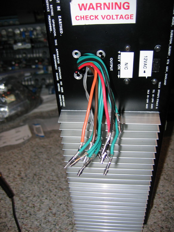
Crimping up the pins for the new interconnection cable connector was easier than I thought and actually went very nicely. I'm very pleased with how well the pins crimped to the cable using a crimping tool I got a long time ago for something else. I don't know if the tool is the proper tool for these pins but it worked really well. To make certain that things were good I bled a little solder into the crimped connections as well.

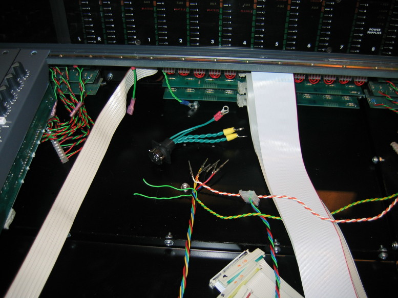
Here are the wires ready to insert into the connector:


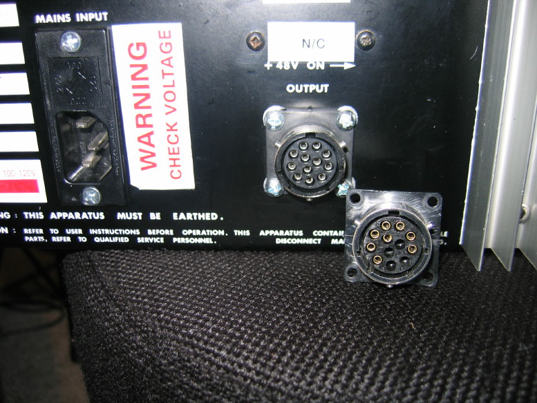
And here is the loaded connector newly fastened to the chassis ready to go. I put the old connector next to it there...you can see they are the same but of course the new connector is fully populated with the new 0V runs whereas the old has 4 spots vacant.


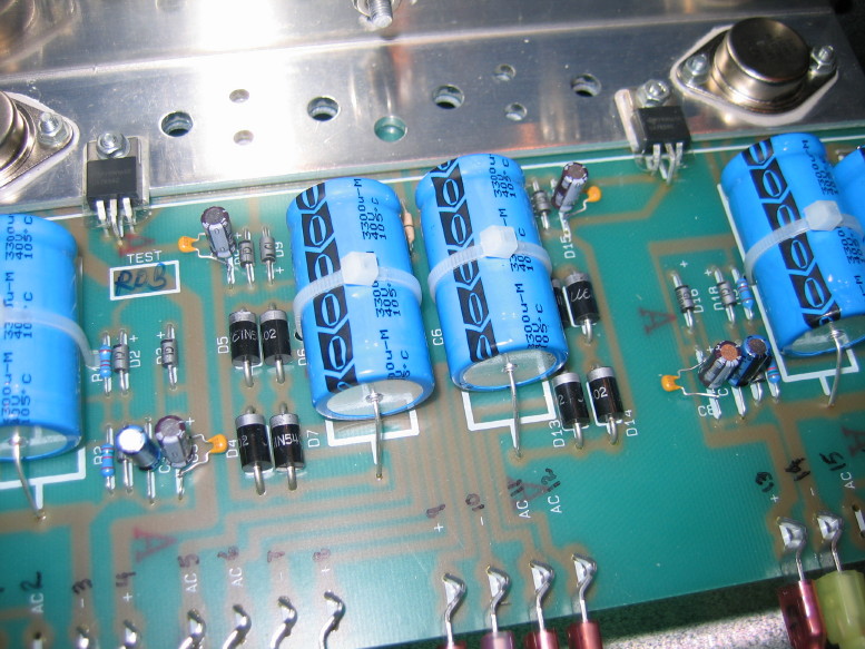
So the other thing I did to finish the supply mods off is add bypass caps to the secondary filter caps. Under advisement I selected XR7 ceramic caps in 0.022uF flavor. COG or XR7 does a nice job with HF bypass. Ceramic is not a popular option in the audio path but this is not in the audio path. XR7 ceramics are cheap. The problem is that their capacitance drops with time and heat and that's why 0.022uF was selected vs. the typical 0.01uF. 0.022uF is still small enough to handle HF bypass well but the higher value will add to the effective life of the parts.

Here they are...4 of them...the little orange ones...


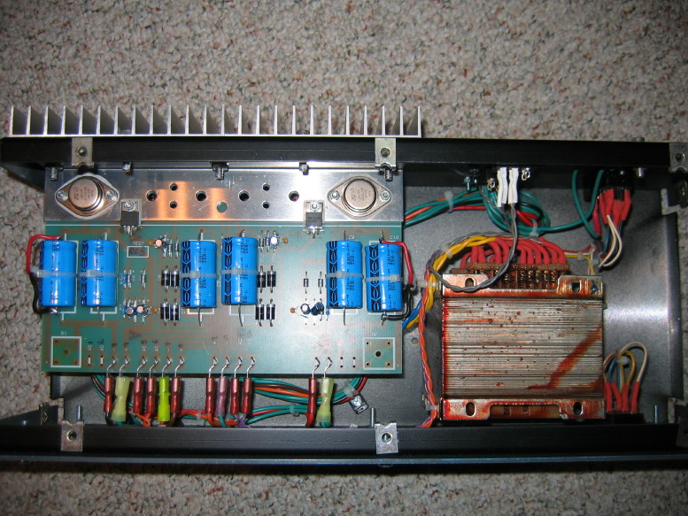
Last pic before it gets closed up and ready to interface with the mixer frame:


So all in all here's what I did to the PSU:

  • Replaced all electrolytics with good quality Vishay and Nichicon parts and improved conductivity of filter caps to PCB
  • Added HF bypass caps to secondary filter caps
  • Replaced/upgraded bridge rectifiers and direct-mounted to back panel to interface new heatsink
  • Reconfigured rectifier-to-filter cap wiring for better continuity
  • Fabricated custom heat management where there existed none and moved heat generating components as necessary to take advantage of the new sink; modified PCB to allow for better cooling from underneath PCB
  • Reconfigured the ground scheme to follow best practices for better HF shunting and general protection
  • Replaced interface connector with new part and repinned to accomodate new ground scheme
  • upgraded 24V regulators to better parts with higher quality insulators
  • installed upgraded power transistors for audio rails and utilized higher quality insulators
  • Eliminated "Earth Lift" function
  • Eliminated +48V defeat switch
  • Added switching function for 12VAC power

Here is a pic of the PSU in stock trim...

Knowing what I know about how the repinning went in the PSU gives me encouragement for how easy it will be to repin the connector on the mixer frame, and that's all that's left before I power test the frame and then load the master section and test it out.
 
Gettin' there...

Almost ready to fasten the power connector to the mixer frame. All the pins are mounted and I've inserted all the ground wires.

 
I have done many really dumb things and I will continue to do them.

Cooking my minty Tascam 58 is one of them and it was pure carelessness on the first count and brazen hammer mechanic the second time.
 
Huh!

I didn't know it would feel like this...

Its alive...


I can't quite put my finger on it but I guess I've been so wrapped up in grounding schemes and power supply mods and structural mods...I forgot what it was like to actually push buttons and route things and to see lights dance around...

Something is *TOTALLY* wacky with the headphone out so I've currently got the cans plugged into the monitor out jacks with some adapters.

I was a little freaked out at first because the meters were doing some strange things...all fine at first and then they'd slowly crawl up and not consistently between each meter...and they'd get brighter and then dim and I thought "oh boy what did I mess up"...then *poof* they'd be normal...they would still respond to signal but would just never drop past their parked level. They've been fine for a couple hours now. Maybe something was just waking up.

Anyway, aside from the wacky headphone thing Everything else seems happy and healthy.

The wacky headphone thing is this: distorted and left and right fields are NOT behaving appropriately...If I have two channels routed to two groups and those are panned center the level is low...pan one group right or left and it gets much louder...pan one hard left and the other hard right and all is fine as long as the fader is all the way down on one group. Bring the fader up and there is really wierd comb filtering and phase distortion as you approach the same level as the other fader. Get them the same and the signal cancels out. So there is something wrong with left and right signals to the headphone amp. I'll deal with that later.

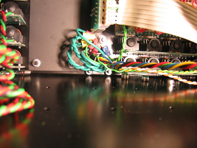
Here is the new ground point...yeah, I know. Looks like Clark Griswold got ahold of it but it is a solid ground point...very effective ground continuity all across the frame and back to the PSU chassis. The heavy green wires are all the 0V connections back to the PSU as well as the PSU chassis to mixer frame common...


You wanna know just how good the grounding is on this thing? Granted this is with only two channels loaded in the frame, but with those channels at unity and roued to all 8 groups and THOSE at unity and the main buss at unity and the monitor out cranked, I can make a call on my cell phone and set it ON THE MASTER SECTION and you can't hear anything from the cell phone transmission. :eek: It'll be interesting to try the test again with all 32 channels loaded and with the studio connections hooked up. That'll be the real test, but so far so good.

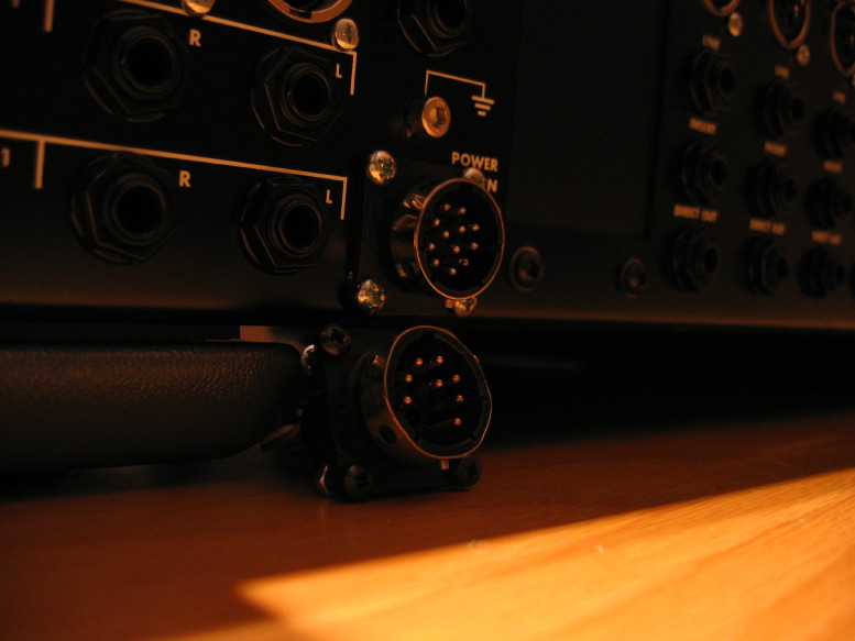
Here's the power connector on the back of the mixer. Looks all nice and new. Old one sitting there below it...It is nice having a round power connector again as you can see the original one took a beating at some point...it was always a chore to get the power cable hooked up.


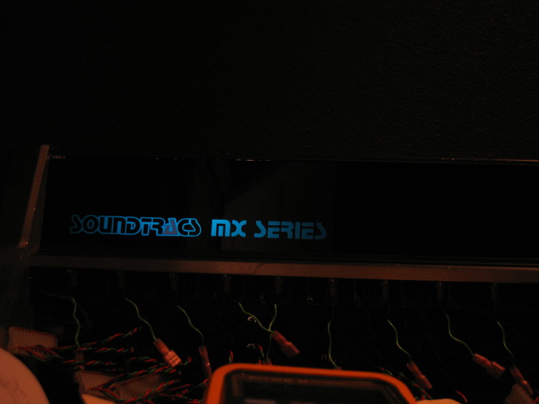
Check this out...pure 80's, folks...there's a PCB behind the meter bridge that I thought was a fuse PCB but the wiring wasn't consistent with that purpose, and then I was told it is a light board...to backlight the logo in the meter bridge. Ssssssswwwweeeeeeet.


A couple impressions so far...It sounds pretty good, especially in the low end. I'm just reproducing 160kbit wma audio off my laptop through a Tascam US-224, so take the impressions with a grain of salt, but the top end sounds mellow and the bottom end is quick and full. Not too jazzed with the middle...its kind of fuzzy and murky, but all the caps are original and IMO Soundtracs skimped on some of the values. I have a set of caps to upgrade two channels so that will be interesting. But it sounds nice, and then when I messed with the eq...huh! I'm not one to really understand or buy into the whole "British eq" thing...I'm too inexperienced with mixing to really understand it...all I know is that I've never really met an eq I liked...one that did something for me...well, this is the first time an eq did something for me. I played with the hi shelving eq to see what I could do with that mellow top end and it turns it from mellow to nice without getting in the way, and then I was messing with the upper mid band and it made my heart rate go up a bit...it brought out some exciting things in the music, like nice meaty upper mid bite that can get in your face without being harsh and the lo shelving brought LF with power and presence that is clear...so that's all a real treat.

One last pic for now...

 
Okay...

So just to update, the whacky meter problem has come back and isn't going away...this is where they park all the time:


I'm getting some assistance from a couple sources but so far no dice.

I've double checked that the problem is not related to the ribbon cable I made up to interface the master section and the meter PCB. I also confirmed good grounding to the meter PCB, and reseated all 26 of the IC's on said PCB.

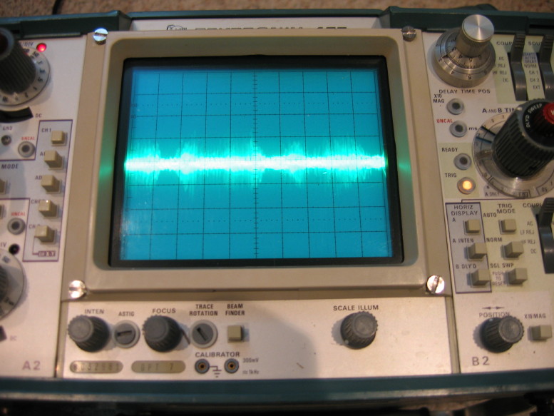
It has been suggested that maybe the PSU is oscillating. Here's what each power rail looks like to my oscilloscope when the VOLTS/DIV is set to 50mV and TIME/DIV is set to 2ms, AC coupled:


I honestly don't know what oscillation looks like on a scope.

So I've got a couple more things to check/test...It wasn't doing it before the last mods to the PSU with the ceramic bypass caps but I really don't know if those could elicit oscillation...that's way over my head.

On a positive note I'm well along getting 8 of the input strips cleaned up, and I did figure out the strange headphone problem: I had soldered my ground lead to the side of the Rean style jack that breaks when the plug is inserted. Good one 'beats... :) Moved the lead to the other side of the jack and all is good now.
 
Call me a simpleton, and ignorant.

But is this happening as a result of you short-loading the bus with strips? Does it need to be fully loaded to even out the meters or something?
 
Hm...I don't know.

I can tell you I wondered if that was an issue even just as far as exposure to RFI in the environment...that ribbon cable just laying there like an 8 foot 40-conductor antenna, but I can't hear anything in the headphones.

You all might think I've been going overboard with all the grounding mods but here's the deal...there is an AM radio station 0.1 miles from my house with a 200 mile service area...5,000 watts of pure RFI nightmare.

I have determined that what I'm seeing on the scope is audio from the radio station and its everywhere.

Working through some other tests with a friend of mine that are focused on assessing what is getting into the system from the environment and not yet tackling the meters but we'll get there.

The thing about the meter issue is that it totally went away for a little bit. I think there is a problem in the system and that its not a symptom of the current state of the mixer (being unloaded) but it is a great question which I'm adding to the mix of possibilities and things to test.
 
So all in all here's what I did to the PSU:

Replaced all electrolytics with good quality Vishay and Nichicon parts and improved conductivity of filter caps to PCB
Added HF bypass caps to secondary filter caps
Replaced/upgraded bridge rectifiers and direct-mounted to back panel to interface new heatsink
Reconfigured rectifier-to-filter cap wiring for better continuity
Fabricated custom heat management where there existed none and moved heat generating components as necessary to take advantage of the new sink; modified PCB to allow for better cooling from underneath PCB
Reconfigured the ground scheme to follow best practices for better HF shunting and general protection
Replaced interface connector with new part and repinned to accomodate new ground scheme
upgraded 24V regulators to better parts with higher quality insulators
installed upgraded power transistors for audio rails and utilized higher quality insulators
Eliminated "Earth Lift" function
Eliminated +48V defeat switch
Added switching function for 12VAC power


is eliminating the phantom power defeat switch a common mod on these?
can u still turn it off/on on the individual channels?
 
The phantom switch I eliminated was a global switch at the PSU. Each channel has phantom enable switches as well.
 
You all might think I've been going overboard with all the grounding mods but here's the deal...there is an AM radio station 0.1 miles from my house with a 200 mile service area...5,000 watts of pure RFI nightmare.
:eek::eek::eek:!!!!


.1 mile??? OMG...do I see a room sized Faraday Cage looming in the future?:confused::D I believe Electric Ladyland had to be enclosed in one. Must have cost a fortune though. But what's a few $100k when you have the money for 2 24traks and other associated Studio stuff.:rolleyes::D

Like these...sheeeezus
http://www.gearslutz.com/board/phot...old-recording-studio-construction-thread.html

http://www.gearslutz.com/board/phot...cts/341598-bridge-recording-studio-build.html


unfreakingbelievable!
 
Just asking as my big carvin mixer the previous owner had to install phantom on/off switches on several channels as it only had an on/off and if you plugged in certain regular mics with phantom power on it would do weird stuff.
 
Its fixed...the whacky meter problem.

I got some major help from Rick Chinn at Uneeda Audio.

We tracked it down to a missing ground. The problem was ultimately the result of all my ground system changes but this is just a reminder of how goofy some of the grounding used to be...its "right" now and I'm on my way.

Also added ceramic bypass caps to the local filter caps in the master section to help kill RF from the radios station down the street. The improved grounding and the bypass caps has made a measurable improvement in the noise floor as well as the RF rejection abilities of the system.

Next up: clean the faders in 8 input strips, and put 'em back together...everything else is cleaned up for 8 of the strips and I've cleaned all the knob and switch caps already for the other 24 strips.
 
8 out of 24 ain't bad...

I'm of the general mindset at this point that I'm spending too much time fixing/refurbishing gear...when it becomes the thrill just to have some of the parts off the floor and out of the little baggies...

On to the next 8...

 
I couldn't agree more!

I'm of the general mindset at this point that I'm spending too much time fixing/refurbishing gear...when it becomes the thrill just to have some of the parts off the floor and out of the little baggies...

On to the next 8...

I couldn't agree more. Cheers! :drunk: ....... ;)
 
Back
Top