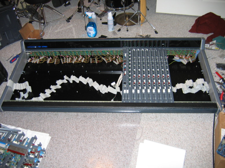
I got all the jack PCB sets up to snuff...that includes modding for a new ground lead, cleaning out the TS/TSR jacks, deoxidizing the silver contacts in the XLR jacks, and re-punching the wiring in the connectors that mate with the PCB's to make sure there is good contact there. That covers all 136 jacks which are contained in 5 jack PCB sets (4 input sets and one master set).
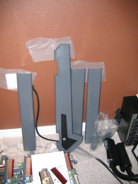
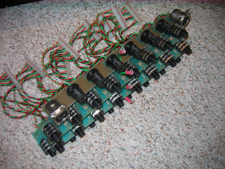
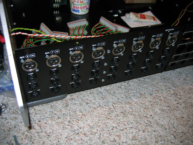
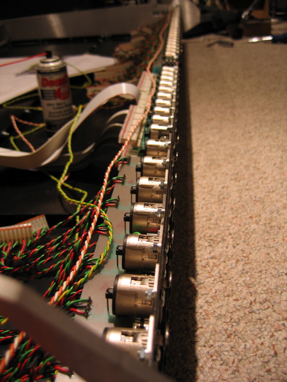
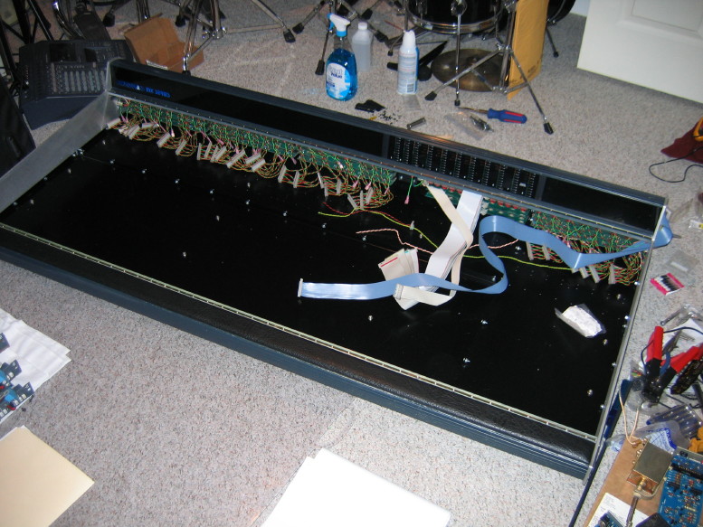
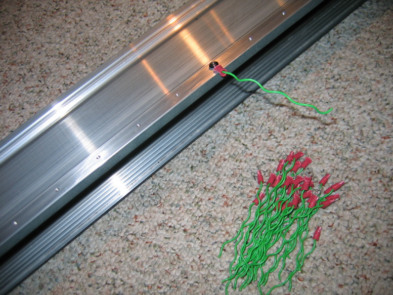
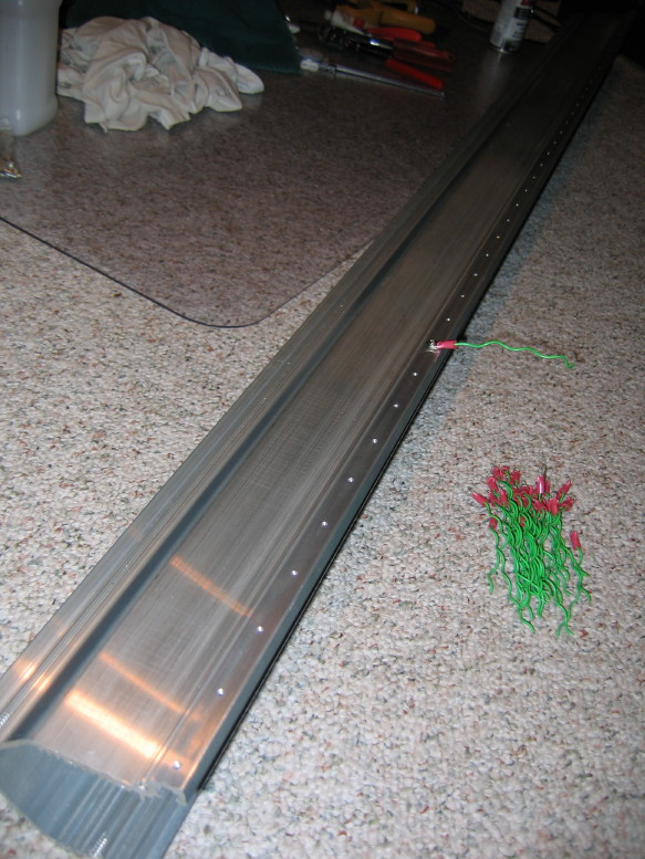
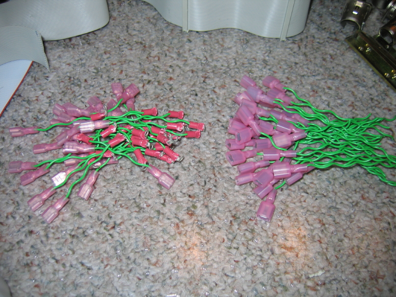
Here is one of the input sets. You can see the new little grounding pigtails coming out of the center of each PCB...the green wire with the pink crimp ring terminal. The wire is recycled from the power supply mods. Its good wire and there was enough for all the tails on all the PCB's:
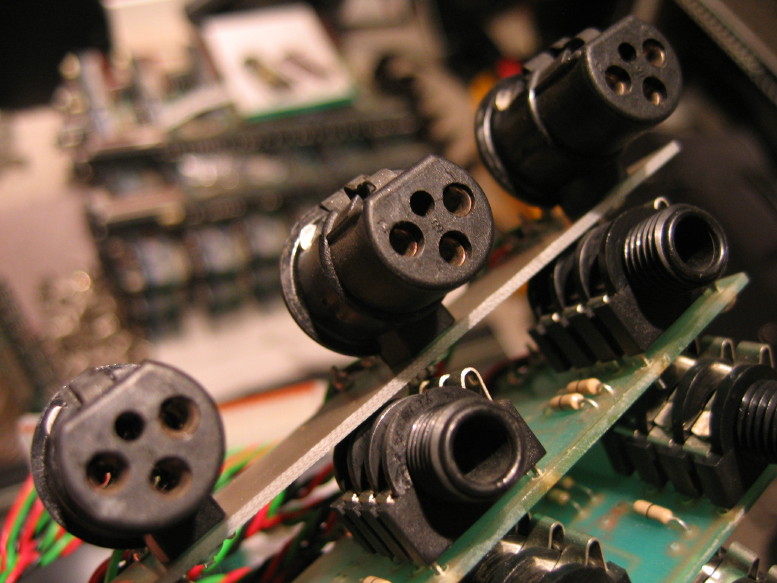
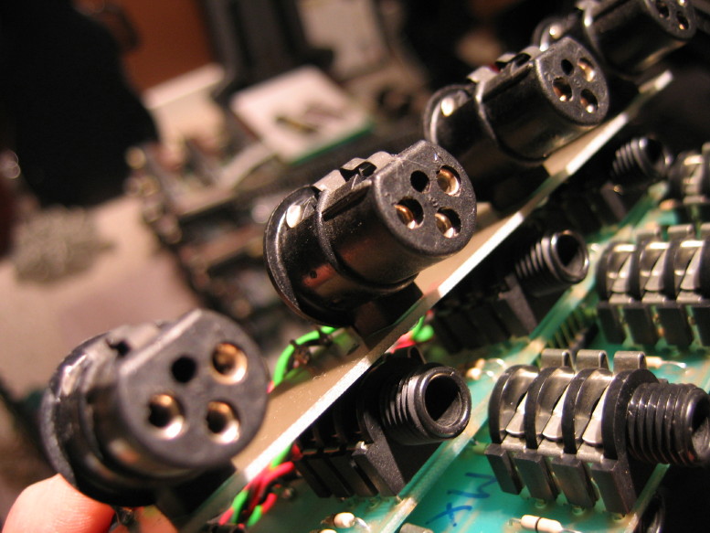
Check out the before and after on the cleaning of the XLR jack contacts...I used Tarn-X and a pipe cleaner, then rinsed with water and set to dry in front of a little heater...
BEFORE:
AFTER:
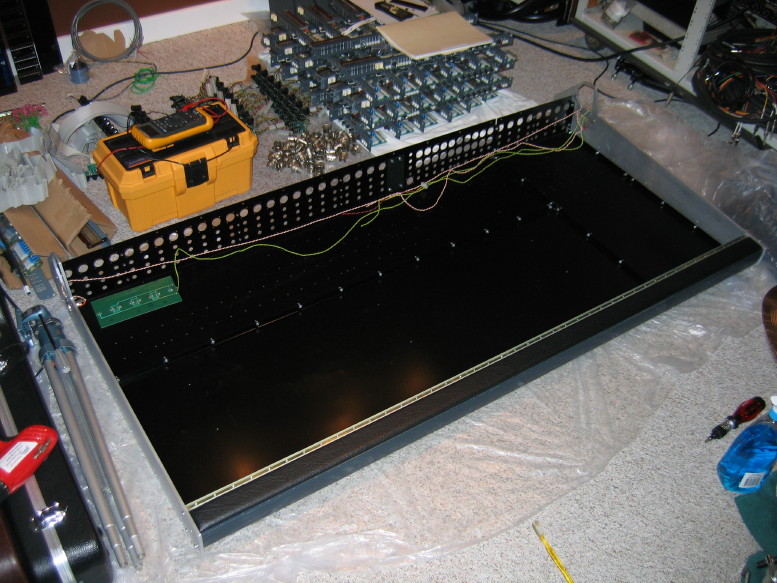
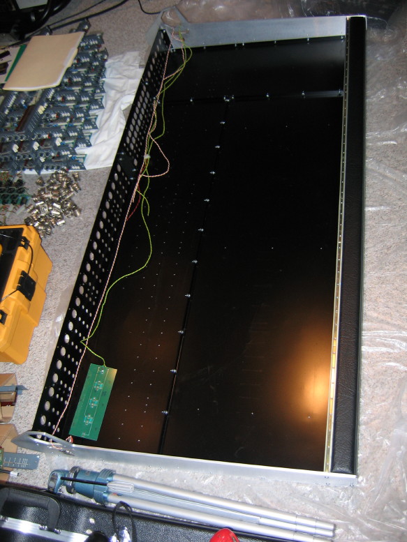
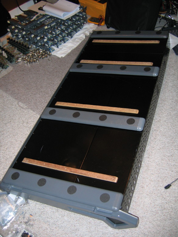
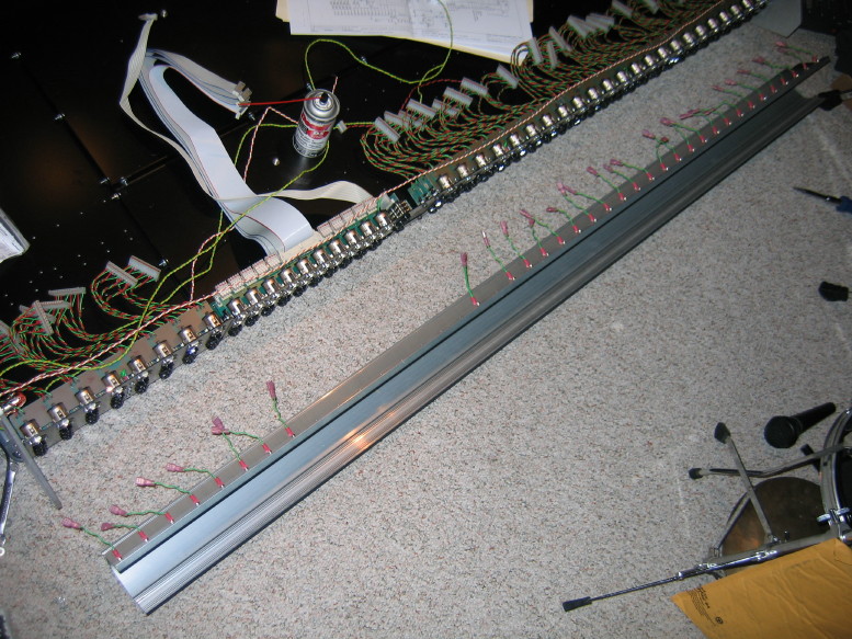
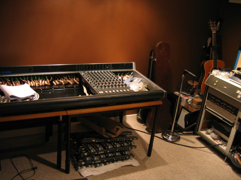
Started getting the jacks reloaded last night.
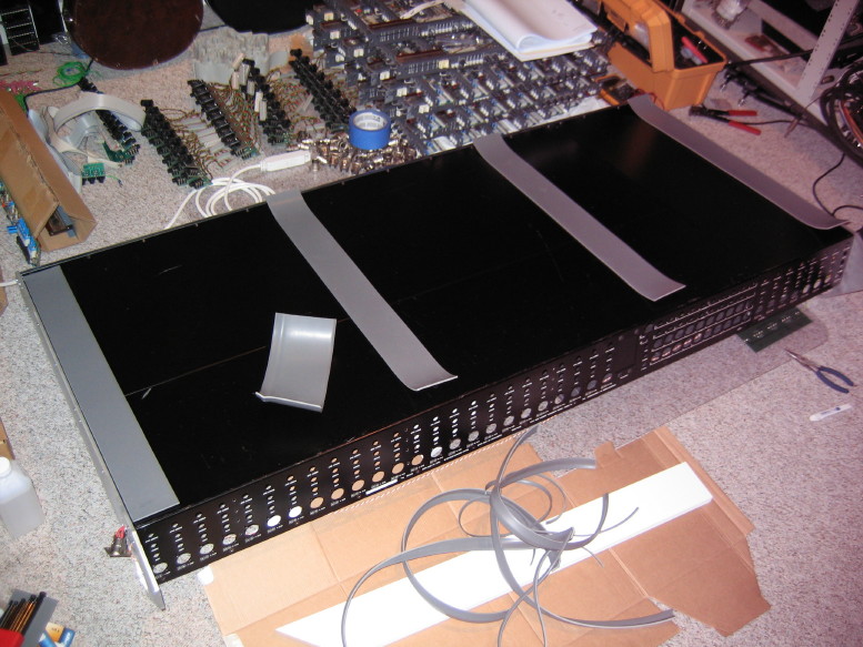
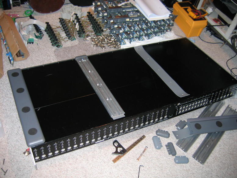
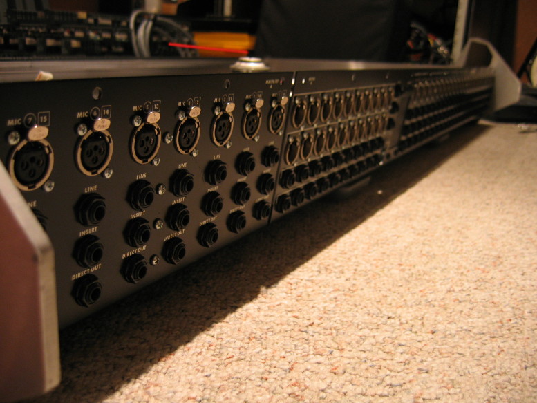
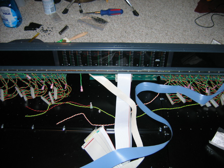
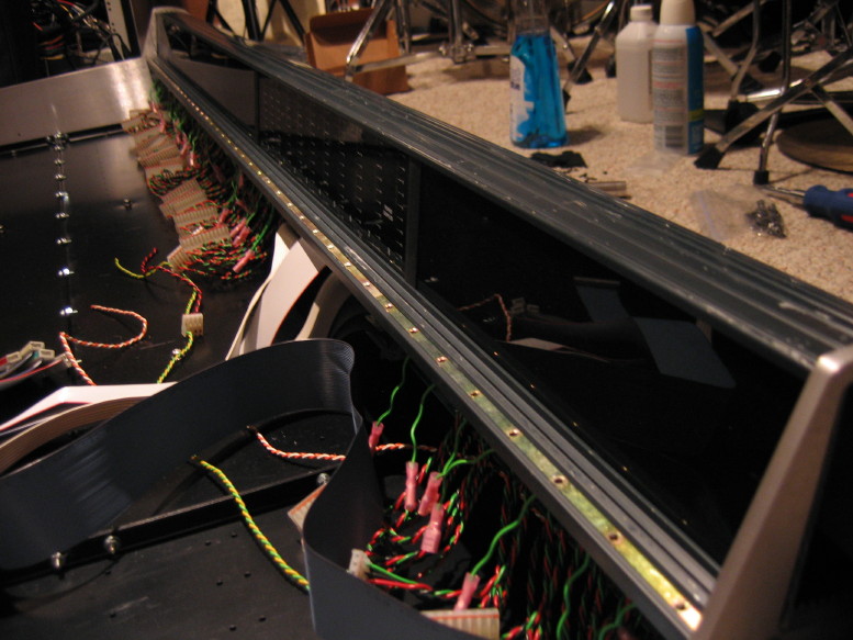
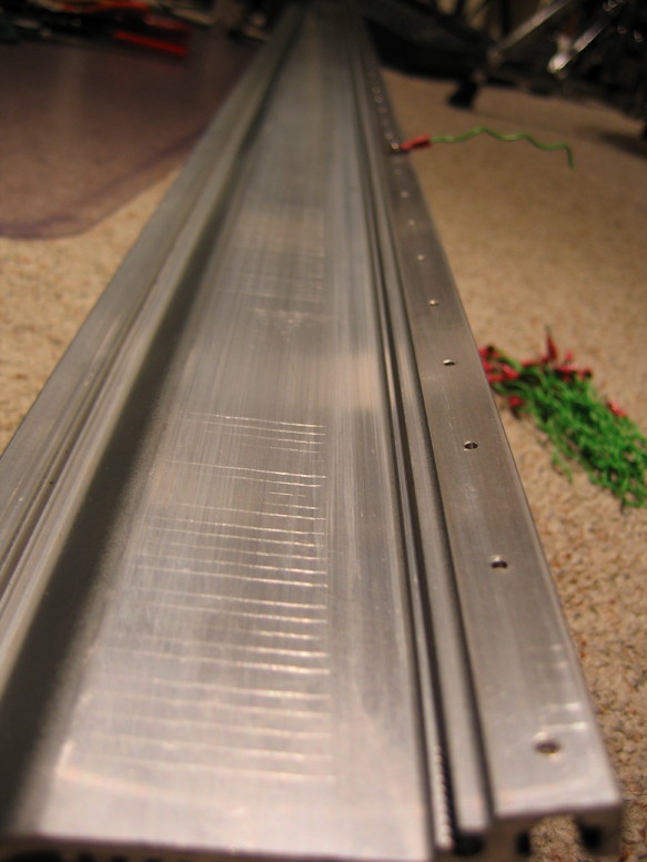
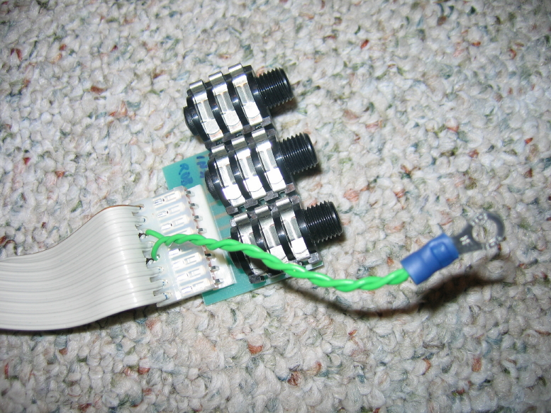
You can see one of the new grounds lead in the middle of the XLR jack PCB going to the backplane in the first pic, and then you can see the 4 screws running down the center of the jack sets which creates the ground lug for each of the 4 jack PCB's in the set. Lookin' shiny!
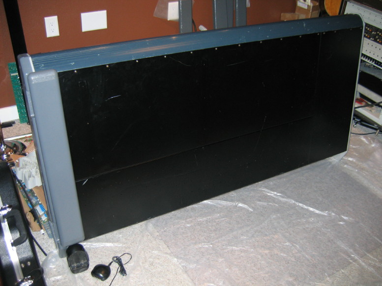
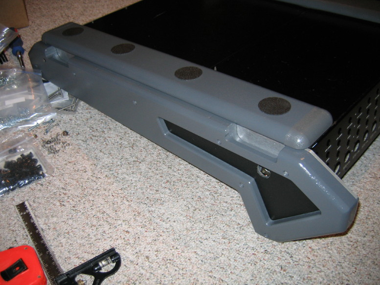
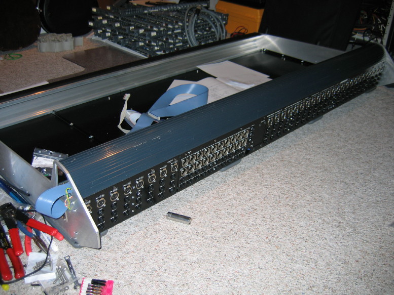
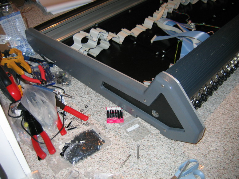
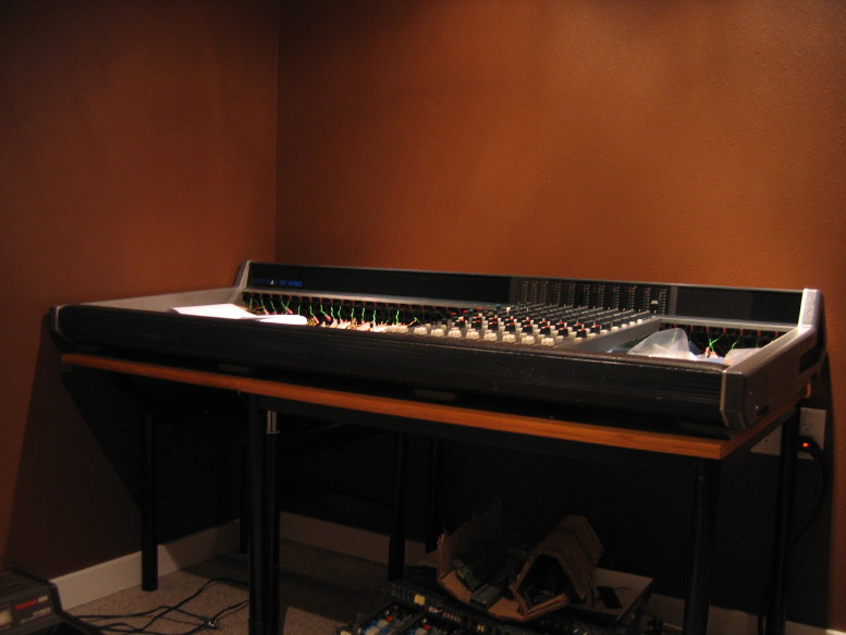
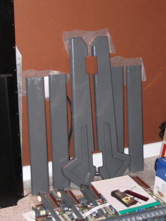
Once the jacks are all back in then the meter bridge goes on and the side panels can be mounted. At that point the frame will be ALMOST complete...just need to get the pins for the connector and wire up the power interface.
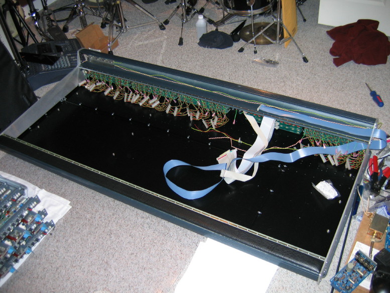
I also made up the new ribbon cable for the meter bridge (old was damaged and the new needed to be longer with the move of the 8 input strips to the right of the master section).
Here's a plot twist on the power connector interface...So I was just about to drop $80 on a new set of Hirose JC/JRC connectors, make up a new cable, etc. etc. Again, this is all because I need at least 12 conductors passing through the interface to handle the new ground-scheme, and, not knowing who makes the stock connectors and not being able to de-pin them and
also being stuck with the stock panel-mount connectors short-loaded with only 8 of 12 pins (and not knowing what brand/model pin goes IN there) I was bent on just starting over with the interface cable and connectors. Well, I was in the boneyard at my favorite local electronics shop and sitting there were
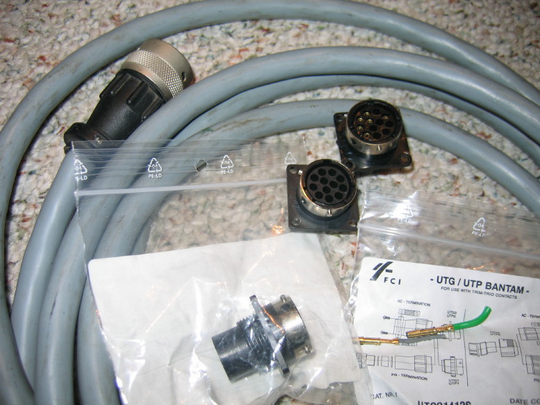
TWO BOXES of the IDENTICAL panel mount connectors to what is on my mixer in stock trim. Each connector in its own little baggie with all the model number info and a type reference for the pins. I paid $2 for a set of the male and female panel mount connectors, and with new info in hand was able to find the proper pins and sockets for the connectors at Mouser! In the end it will cost about $17 total for the connectors and pins and sockets, but
I don't have to make a new interface cable.
")
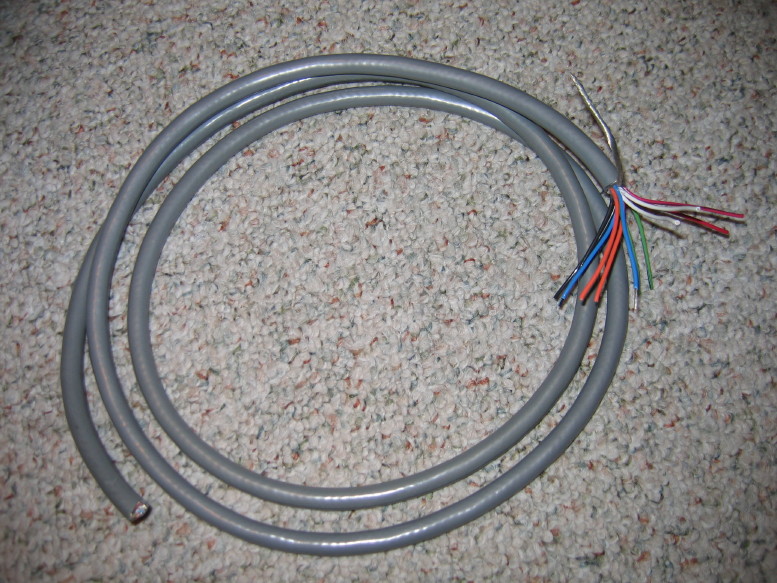
There is really nothing wrong with the stock cable. The connectors, though they utilize some plastic, work well and are quality parts. The ONLY drawback to the is that the cable is not shielded and since plastic is utilized there is no way for the ground reference from the PSU chassis to propogate to the mixer frame over a cable shield and through the connectors. The overall cable shield is an added protection against environmental
EMI/RFI. At this point it is worth it to me to take the risk of running the chassis-chassis ground through the cable rather than an overall cable shield in order to save time and money...each PCB has local power filtration. If it turns out to be a problem I can always deal with it later.
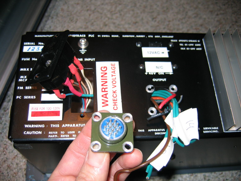
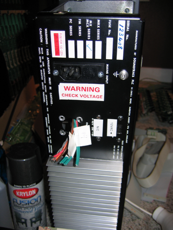
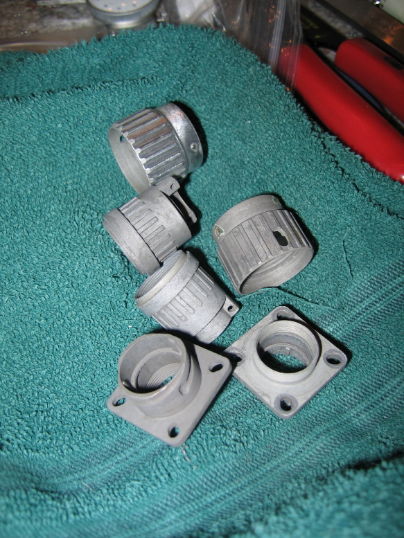
Here are the new connectors with the stock cable and one of the old panel-mount connectors:
")
")