famous beagle
Well-known member
I didn't get past step 2 last night. I'll do that today. That result was only for step 2.
For steps 1-2, I measure 1.409(ish)K ohms.
I'll take the other measurements tomorrow. Thanks
Hm. Interesting. Stay tuned. I'm not sure but I think U104 might need replaced.
I'll have some more things to probe later.
")
Well duh...of course the result of step 3 (measuring the voltage between those BUSS B PCB) was 0 volts. Power comes from the MONITOR PCB to the BUSS B PCB via the M BUSS PCB (that goes for ALL the mixer channel cards by the way)...so with the M BUSS PCB removed there is no power to be had.
So at this point I'm thinking a couple options are:
1. Now that you know where Q101 is, go back a few posts and test for test tone at the S terminal of Q101 on the BUSS B PCB to confirm signal is getting to that point
2. Find a way to jumper power and ground from the MONITOR PCB to the BUSS B PCB so we can do step 3 of my last set of instructions
3. Say "screw it" and shotgun U104 on the BUSS B PCB (shotgun is the term used when you blindly replace a part you *think* might be the cause of a problem but you don't really know for sure) and put a new part in.
Think about any or all of those suggestions and I can help you with any/all of them.
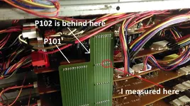
Outside of that, reinstall the M BUSS PCB and let's check the following voltages at P102 of the BUSS B PCB:
1. Meter set to DC volts, measure between pin 5 and pin 8
2. Meter set to AC volts, measure between pin 5 and pin 8
3. Meter set to DC volts, measure between pin 6 and pin 8
4. Meter set to AC volts, measure between pin 6 and pin 8
Report back
Yes MC14049 through-hole 16-pin dip package.
Here's another source:
Motorola - MC14049UBCP - IC, CMOS. Hex buffer.
Ignore the CP. a lot of times those suffix letters are an identifier created by a common application, but there is no difference in the part itself.
Check those voltages, let me know.
Good gracious...$9 to ship a 16-pin dip IC.
Both of your links were the same thing. Was that intended or was there another different link you meant to post?

And I'm an ignoramous.
I'd go with that last option. I know you get a smaller quantity for your money, but I am less concerned about non-genuine/counterfeit parts with that last option.
Well duh...of course the result of step 3 (measuring the voltage between those BUSS B PCB) was 0 volts. Power comes from the MONITOR PCB to the BUSS B PCB via the M BUSS PCB (that goes for ALL the mixer channel cards by the way)...so with the M BUSS PCB removed there is no power to be had.
So at this point I'm thinking a couple options are:
1. Now that you know where Q101 is, go back a few posts and test for test tone at the S terminal of Q101 on the BUSS B PCB to confirm signal is getting to that point
2. Find a way to jumper power and ground from the MONITOR PCB to the BUSS B PCB so we can do step 3 of my last set of instructions
3. Say "screw it" and shotgun U104 on the BUSS B PCB (shotgun is the term used when you blindly replace a part you *think* might be the cause of a problem but you don't really know for sure) and put a new part in.
Think about any or all of those suggestions and I can help you with any/all of them.
Outside of that, reinstall the M BUSS PCB and let's check the following voltages at P102 of the BUSS B PCB:
1. Meter set to DC volts, measure between pin 5 and pin 8
2. Meter set to AC volts, measure between pin 5 and pin 8
3. Meter set to DC volts, measure between pin 6 and pin 8
4. Meter set to AC volts, measure between pin 6 and pin 8
Report back
Measuring the pins from the M BUSS PCB is fine. Good logic/thinking there.
Those DC voltage results are fine.
Do you have AC volts range adjustments? I don't know what meter you are using. Mine auto-ranges so I didn't even think to ask. We're going to be measuring in the millivolts so set the range to whatever the smallest voltage is.