famous beagle
Well-known member
I figured as much.
Okay. So next we need to move upstream one step and see if we have signal at the input of the switching transistors. This may get tricky with just standard probes because I can't see how easy it is to get to the transistors.
You are looking for Q101 on the BUSS B PCB. It is a little JFET transistor. It'll have 3 legs and the legs should be labeled D, S and G on the board. Leaving all conditions the same as the previous test, I want you to put the + probe on the 'S' terminal of Q101, and leave the - probe on pin 2 of P108.
What do you get on the multimeter?
-OR-, put up a pic of what you are working with if you can't get to stuff, and we'll see if we can ascertain a work-around.
This is a JFET:
View attachment 97673
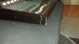
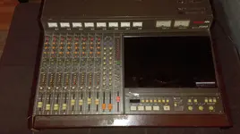
Ok, I've hit the first hurdle. I think I may have to take the knobs off the front so I can pull the monitor assembly out a bit because I can't seem to locate Q101. I found a Q104 at the end of a line of four JFETs, but I can't see the names of any of the other ones, and there's an IC in the way.
Like I said in the PM I sent you, my manual is missing several pages from the maintenance portion, and the layout for the BUSS B PCB is one of them.

Oh, and I should still be measuring AC voltage, correct?
")
