ausrock
Well-known member
Marik,
It may be similar to the pics you posted on page 2, but the variations required enough modifications to the PCB to regard this as "version III".
What I have just noticed is that either (or both) the larger 22uf electrolytic near the XLR connector and the 152 ceramic next to it have been generating enough heat to start to fuse the two together as they were virtually in contact. On my other ECM, even though there is a gap between the two caps, there are signs that heat is causing changes to the cap surfaces.
Gus,
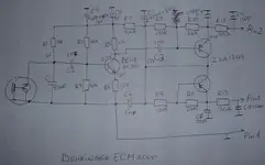
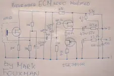
The two small ceramics at the connector end are 222. The other two are both 152. The larger electro is 22uf 35V. The small electro in that group I can't identify other than it is 50V. The larger blue electro is 47uf and the small one next to it appears to be 22uf and the last electro at the capsule end is possibly 10uf. The polyester at the end is 332J.
The transistor is marked .... S9014 C 331, and the IC is A1349.
It may be similar to the pics you posted on page 2, but the variations required enough modifications to the PCB to regard this as "version III".
What I have just noticed is that either (or both) the larger 22uf electrolytic near the XLR connector and the 152 ceramic next to it have been generating enough heat to start to fuse the two together as they were virtually in contact. On my other ECM, even though there is a gap between the two caps, there are signs that heat is causing changes to the cap surfaces.
Gus,
The two small ceramics at the connector end are 222. The other two are both 152. The larger electro is 22uf 35V. The small electro in that group I can't identify other than it is 50V. The larger blue electro is 47uf and the small one next to it appears to be 22uf and the last electro at the capsule end is possibly 10uf. The polyester at the end is 332J.
The transistor is marked .... S9014 C 331, and the IC is A1349.

")
")
") Lowered the self noise? Ta
Lowered the self noise? Ta