Well, howdy guys.
")
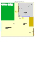
Ok, here is a couple of drawings. A PLAN VIEW, which shows the TOP Module(F), and the wall Modules. I've increased the length from 48" to 60" as per Shellshocks request. Guys, this is my attempt at showing a solution based on Shellshocks criteria, which at best screams for simplicity

, as well as some compromises based on the criteria limitations.
Compromise 1. Budget. Means MOST BANG for the buck.
Compromise 2. Limited space Means BASIC size, translates into using MDF sheet dimensions to size Modules.
Compromise 3. Limited tools. Creates problems for tolerance and accuracy of sizing materials.
Compromise 4. Limited source for materials. Homedepot pretty much.
Compromise 5. Limited skillset. Means showing EACH STEP...translates into time. This won't happen overnight. But, it will be the FIRST FULL SET OF PLANS for a basic all purpose/limited transmission loss, simple VOCAL booth. YEA!
")
Lets talk.
Ok, here is the beginning. We need to define some ABSOLUTES first though.
Shellshock, I need to know EXACTLY how high the ceiling is, from carpet to ceiling. I'm talking within 1/8". Let me explain something here. The very first criteria of this project, and that which defines EVERYTHING ELSE, is ....
"KNOCK DOWN"


Since this is in an apartment, it MUST be assembled and DISASSEMBLED and moved. This translates into MODULES. Seeing as this is a box, that means SIX sides, or six Modules. Plus ONE, which is an alignment panel for the isolation material, which STILL needs to be discussed as soon as possible. But later. For now, we need to discuss some other things. Mainly, construction PRECISION.
Guys, since this is going to be a Knockdown unit, this means that DRYWALL is out of the question, since gypsum board is easily damaged, needs joints taped and mudded, and a texture layer applied. Forget it. What we need is a solid material. It MUST be built from materials that are designed for tight joinery, has a good Mass/thickness ratio, easily machined, is reasonably priced and can be finished with simple methods. However, thats another thing. The finish. But more on that later. What this amounts to is simple. MDF. No other SOLID panel meets the needs of Iso construction like MDF.
However, there is something everyone needs to understand here. And this is the MOST IMPORTANT issue in working with SHEETGOODS..or Panels as they are refered to in woodworking circles.

And that is SQUARENESS.
PERIOD!!!
Because we are building in THREE different planes, alignment of panels becomes absolutely critical. This means CUTTING with precision layouts. ONE out of square panel creates SO MANY problems, you don't even want to go there. Soooooooooooo...I'm going to have to show how "I" build large panel BOXES. Because this is a big ole box..thats all. So what if it has a door, or a window...its still a box. And there are a MILLION ways to build a box. However, given the criteria of this project, it creates a mirad of problems for KNOCKDOWN. Basically, we are going to build a CRATE. A SEALED TWO LEAF CRATE with a door and a window. Since Shellshock has to assemble LARGE 4'x5' 4'x8' and 5'x8'(nominal dimensions) modules in a very small and cramped space, ASSEMBLY sequence, and ease is of prime importance. This dictates the detailing of the modules. Hence my delination of the Module JOINERY.
Once the Modules are fabricated, here is the "planned" component assembly sequence.
1. Lay ALIGNMENT Platform in corner of room. This aligns the ISOLATOR material to the FLOOR MODULE(A). It also adds a layer of DECOUPLED mass between the booth and the existing floor. However, due to the fact that the isolation material or other decouplers, is NOT enclosed, it only adds mass to the existing floor leaf. Therefore, it does NOT become a leaf of the Floor module. Note that the placement is ONLY TEMPORARY, as space between the first two wall modules and the existing wall is required to insert and tighten the Fastening bolts at bottom and top of these two walls. Later on that.
2. Lay floor module on alignment panel. Thats the purpose of a 1x1 skirt on the alignment panel and the bottom of the floor module. Although, this is subject to change due to choice of isolator. I've drawn in what I think is the FIRST compromise. Since budget, and availability is one of the criteria, but 703 as the ABSORBER PANELS, is NOT a compromise,

That being said, I believe that we should simply use some 703 as the decoupling medium since this product is NOT ON THE COMPROMISE LIST
. In sufficient size pads, a series a 2" thick x4"x4" pads should do the trick. At least in view of compromise I believe it will NOT compress too much in this fashion. I figure 12 pieces should work fine.I still have some research to do on this. The only other options are Duro 60 Neoprene, or proprietary products such as can be found on the net. However, time, money, minimum purchase, will power
hey, were all human.
AND musicians...hahahahahahaha!
Next, Module B, brought in, raised upright, and leaned agaist wall in front of window.
Next, Module C, brought in, raised upright, and now PLACED on edge of Floor module in correct location, and LEANED BACK against wall. Now Module B is placed on edge of Floor module, and PINS placed in BUTT HINGES, at the inside corner where the two walls intersect. These are actually a device to hold the walls together untill the fastening bolts are inserted at the Floor module and tightened. These are long 1/4" machine bolts, that thread into "integeral" T nuts. I'll post a detail of these later. Because these bolts are long, and have to be inserted into the holes at the bottom of the modules, BETWEEN the modules and existing wall, and then tightened, thats why I said to leave the alignment panel on the floor, away from each of the corner walls about 8". Once the top Module is in place, then slide the unit towards the corner.
Next, bring in the TOP Module, lift into place, which actually "rests" on a "ledge", which is part of the wall modules. Now, insert the Fastening bolts at the top of Modules B & C, then tighten. Just tight enough to be snug. THATS ALL.
Next, bring in Module E. This has the door opening, although the door is NOT installed yet. It will have been PRE FIT, so only the HINGE PINS need be inserted when its time to install the door. Place on edge of floor module. Now insert the CORNER ALIGNMENT hinge pins to hold Module E to Module B. Now insert the fastening bolts through Module E, into the Floor Module(A), Module B, and the Top Module(F).
Do NOT tighten completely yet. Leave 1/8" play for now.
Next, bring in Module D(window module), place on edge of Floor Module, and insert corner hinge pins. Now insert bolts through Module D into the floor Module and Top Module. Do NOT tighten completely. Just barely. This allows bolts inserted through Module E & C and easily into Module D.
Now tighten ALL the bolts through Module E, and the bolts through Mod C into Module D, and the bolts through Module D into the Floor and Top modules.
Next, bring in door, align hinge knuckles, insert pins.
Next, plug lighting and power supply cord into wall outlet. Turn on light. Turn on FAN switch. Lay precut carpet.
Next, insert proposed Absorber panels into their respective locations. These should have been PRE COVERED panels. We still have to discuss/define/decide on some things. In the drawings, I show some blocking in all the corners for stapleing FABRIC over the panels if you so decide. However, precovered panels look better, and its easier to do. Later on that.
Next, fasten "floating" Mic clip in correct location. Insert Mic, and plug in cable to XLR jack in wall. Now, plug mic cable from booth to its correct input on mixer/or other device or interface.
VOILA!! One Vocal Booth!!
Hahahahaha....wish it was that simple. Actually, if it is fabricated CORRECTLY, it WILL BE! However, now comes time for the actual building.
But alas, its bed time. Here is my pics for the night. Study them, and the preceding. There will be more EACH NIGHT. Well, thats it for now. Later.

 ..good lookin out rick


 :rolleyes:") You've got to learn to LOOK
You've got to learn to LOOK