Basic oscilloscope help

famous beagle

Well-known member
Hey y'all,

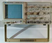
So I just bought my first hardware oscilloscope off ebay. It's mainly just a curiosity, although I would like to make use of it with regard to calibrating tape machines (azimuth, etc.) eventually.

However, it arrived slightly damaged -- the handle is broken. The seller told me he can send me another handle, but before I do that, I wanted to verify that it was still functional.

Since I've never used one before at all, I was wondering if someone could instruct me on a very basic setup I could use to check basic functionality. I know I won't be able to completely put it through its paces, but I want to make sure it's not a dead stick at the very least.

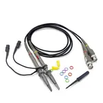
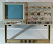
Attached are the scope and probes I have.

Could someone possibly give me a very quick explanation on how I could quickly just make sure it's actually "oscilloscoping" the way it's supposed to be? It doesn't have to have anything to do with tape machines, music, or anything --- just whatever is quick and easy for a newbie like me (assuming that's possible).

Thanks!
 

Attachments

  • Osc.jpg
    Osc.jpg
    122.8 KB · Views: 10
  • probes.jpg
    probes.jpg
    66.7 KB · Views: 10
Did you get the manual? You can check a 1 khz sine wave from any additive synthesizer speaker out, check electric guitar output signal for small levels things like that. Hopefully Dave will be along to give more helpful ideas
 
On the far left bottom corner is a little metal tab. You can clip your probes to that for testing. It says you should see 2v p-p @ 1khz. (p-p means peak to peak. Very top of sine wave to very bottom)
 
Did you get the manual? You can check a 1 khz sine wave from any additive synthesizer speaker out, check electric guitar output signal for small levels things like that. Hopefully Dave will be along to give more helpful ideas
I do have the manual. It's a bit daunting, to be honest, but I'm trying to find the info I need. I'm always watching a few YT videos.

I'm such a newbie that I don't even know how to use the probes. I mean, I know how to connect it to the scope, but after that, I don't really know what to do with them.
 
On the far left bottom corner is a little metal tab. You can clip your probes to that for testing. It says you should see 2v p-p @ 1khz. (p-p means peak to peak. Very top of sine wave to very bottom)
Thanks! I'll give it a shot.
 
On the far left bottom corner is a little metal tab. You can clip your probes to that for testing. It says you should see 2v p-p @ 1khz. (p-p means peak to peak. Very top of sine wave to very bottom)
Most scopes will have a square wave at that terminal and can be used to adjust the frequency compensation which affects the rise and fall edge when displayed. The probes he got look like they may have an adjustment back at the BNC end.

 
On the far left bottom corner is a little metal tab. You can clip your probes to that for testing. It says you should see 2v p-p @ 1khz. (p-p means peak to peak. Very top of sine wave to very bottom)
Ok, I got some action doing that. Everything seems to be working great except for the VARIABLE knob on CH 1. When I adjust this on CH 2, the waveform gets taller or shorter. On CH 1 though, this isn't happening. There seems to a short or something, because when I turn it, the waveform will get squiggly for an instant and then go back. It never gets shorter or taller.

Is this a deal-breaker, you think?

Thanks!
 

Attachments

  • Osc - variable CH 1.jpg
    Osc - variable CH 1.jpg
    213 KB · Views: 6
  • Variable.jpg
    Variable.jpg
    495.6 KB · Views: 5
Most scopes will have a square wave at that terminal and can be used to adjust the frequency compensation which affects the rise and fall edge when displayed. The probes he got look like they may have an adjustment back at the BNC end.

Awesome, thanks! I found it, and you were absolutely right. I got both probes calibrated now in that regard.
 
The scope is a visual multimeter. Grab a few gizmos and have a play. I measures on the up/down axis voltage, and on left to right, time. the timebase controls how fast the trace goes left to right and the other controls select the range, so you could have one square up and down representing a Volt, so five squares is 5 volts - turning the knob one extra click could be X10 - so one square is 10 Volts, or going the other way, .1V If you have a headphone with an unscrewable plug you can connect your probe to the screen and the tip and then play some YouTube tone videos - start with searching for 1Kh tone - and adjust the amplitude control till the trace almost fills the screen top to bottom then speed the timebase up and at some point you will see a sine wave. When you get it stable and static - see if you can read the controls and see the link to 1KHzIf you double or halve the timebase, twice or half the number of complete cycles will be seen. You can even connect a dynamic mic and see it's output. Some probe sets might have a built in 10 or 20dB pad for when you have higher input levels. If you have a test tape, recorded with the head at exactly 90 degrees to the tape edge, playing back the tone will show you the level drop off as you adjust the azimuth. Digital meters on your DAW are quite capable of showing you these small levels nowadays but a scope is the best way to see distortion where the flat top to the waveform is easy to see. They're also good at showing you errors superimposed on the sine wave. If you have a synth or synth plug in with filters and things, it's amazing what happens to a sine wave as you add harmonics - you start to see little humps and bumps in the waveform. with practice, a 1KHz tone with a small amount of 2KHz in it will be obvious.
 
The scope is a visual multimeter. Grab a few gizmos and have a play. I measures on the up/down axis voltage, and on left to right, time. the timebase controls how fast the trace goes left to right and the other controls select the range, so you could have one square up and down representing a Volt, so five squares is 5 volts - turning the knob one extra click could be X10 - so one square is 10 Volts, or going the other way, .1V If you have a headphone with an unscrewable plug you can connect your probe to the screen and the tip and then play some YouTube tone videos - start with searching for 1Kh tone - and adjust the amplitude control till the trace almost fills the screen top to bottom then speed the timebase up and at some point you will see a sine wave. When you get it stable and static - see if you can read the controls and see the link to 1KHzIf you double or halve the timebase, twice or half the number of complete cycles will be seen. You can even connect a dynamic mic and see it's output. Some probe sets might have a built in 10 or 20dB pad for when you have higher input levels. If you have a test tape, recorded with the head at exactly 90 degrees to the tape edge, playing back the tone will show you the level drop off as you adjust the azimuth. Digital meters on your DAW are quite capable of showing you these small levels nowadays but a scope is the best way to see distortion where the flat top to the waveform is easy to see. They're also good at showing you errors superimposed on the sine wave. If you have a synth or synth plug in with filters and things, it's amazing what happens to a sine wave as you add harmonics - you start to see little humps and bumps in the waveform. with practice, a 1KHz tone with a small amount of 2KHz in it will be obvious.
Thanks for all the tips! I'm already having fun with this thing! :)
 
Once you get comfy with it you can do some really cool things, like early science fiction movies. Google Lissajous Figures. you connect audio left to up and down, and right to left and right timebases. Mono gives a diagonal 45 degree line. Different notes to left and right from your DAW produces art! Kept me occupied for months in the 70s
 
Back
Top