sweetbeats
Reel deep thoughts...
One down, one to go!
Got one of the PSU's rebuilt last night. I tell ya...replacing components that aren't on PCB's requires a little more creativity...there were only 4 caps to replace and I chose to replace the rectifier diodes and bleeder resistor, but it took a good chunk of time last night. On a PCB you can heat and suck the solder and the component is easy to get off, but when the guts aren't on a printed circuit board the tails of the components are wound around terminals and so there is a bit more care, time and attention required to get the old stuff off.
Anyway, I succeeded (though I haven't smoke tested it yet...).
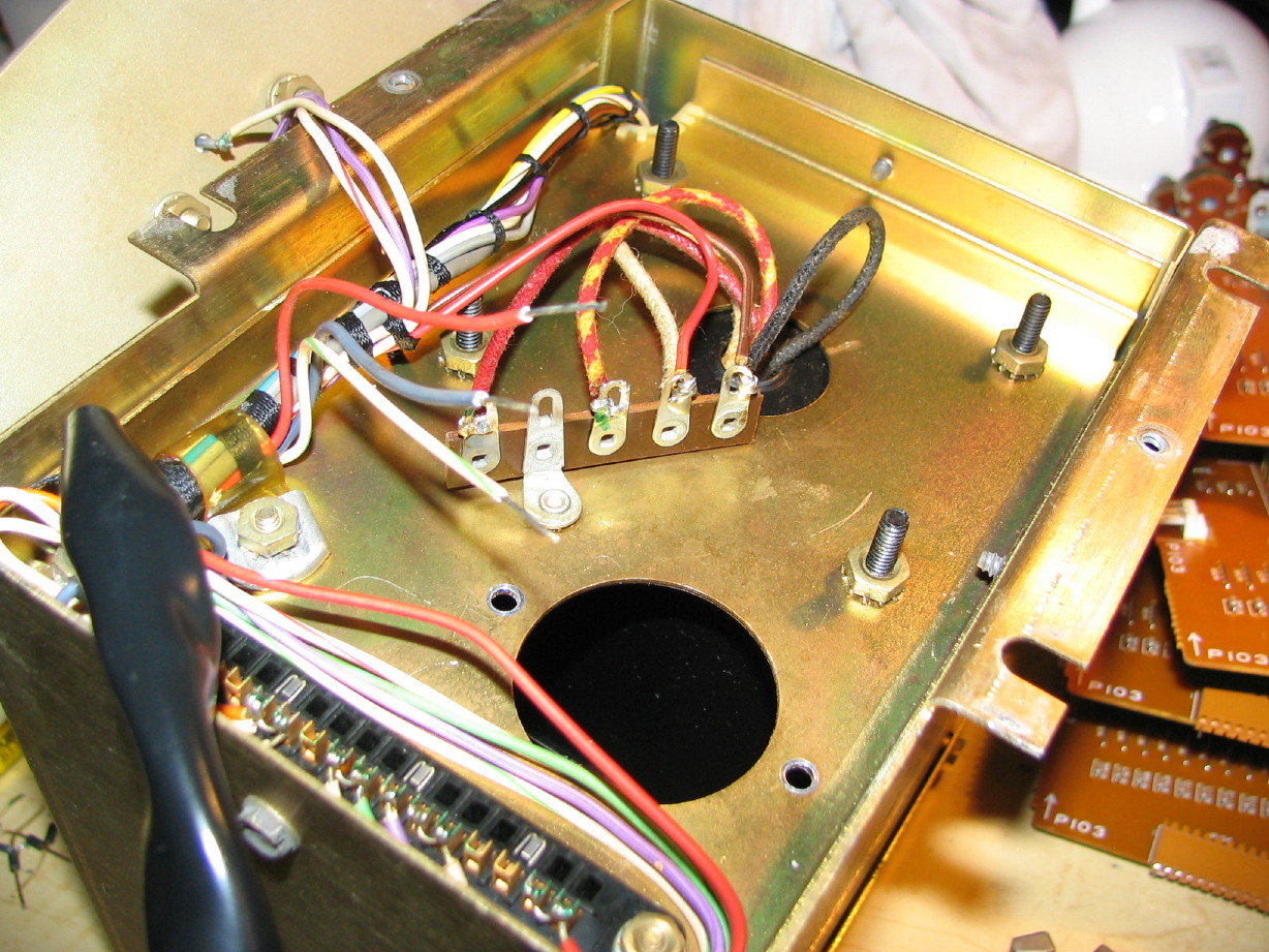
Here is the bottom of the PSU with all the old stuff removed ready for the new stuff to move in...the big hole is where the terminals of the new big filter cap will be, and you can see the three wires that connect to that cap and the terminal strip in background where the diodes will connect:
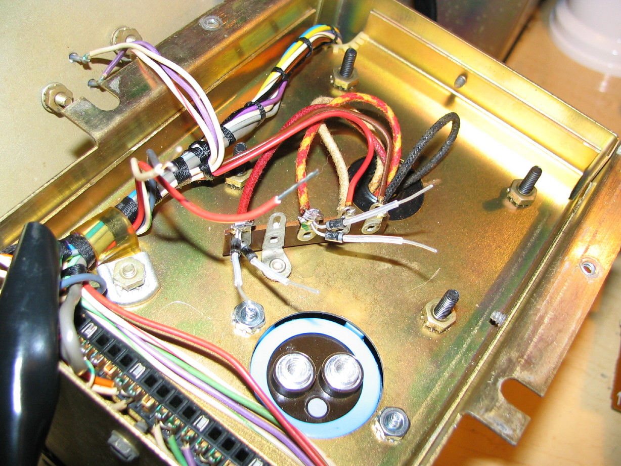
Filter cap in place along with the recitifier diodes:
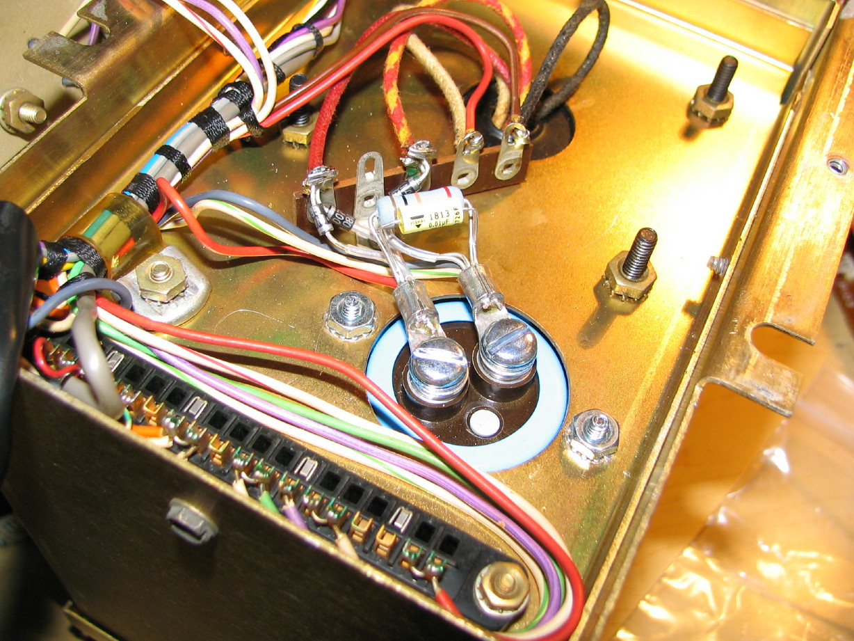
And here's the whole mess put back together along with a 0.01uF bypass cap that was recommended. I crimped each bundle on the ring connector and then filled it up with solder. It is kind of fun to do this kind of work because you get to be a little creative with how you route things and lay certain things out...not that I did it the best way...Open to suggestion on that. Tried to keep safety in mind in routing things to avoid the potential for short circuiting. There is a plate that covers most of these components and, again, this is the bottom side of the PSU which gets bolted to a heavy steel shelf which is bolted to the 440 console frame so very stable and protected but...
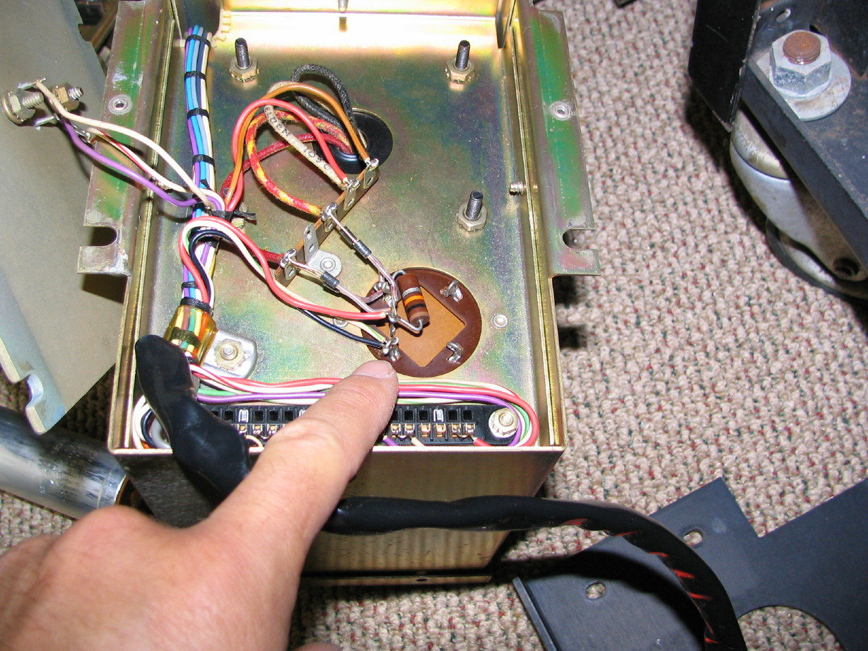
For contrast here again is the before picture of the same area posted somewhere earlier...
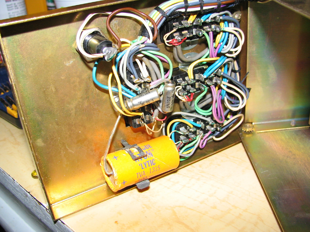
Now to the three caps on the underside of the lid of the PSU...here is the before:
And here is the after:
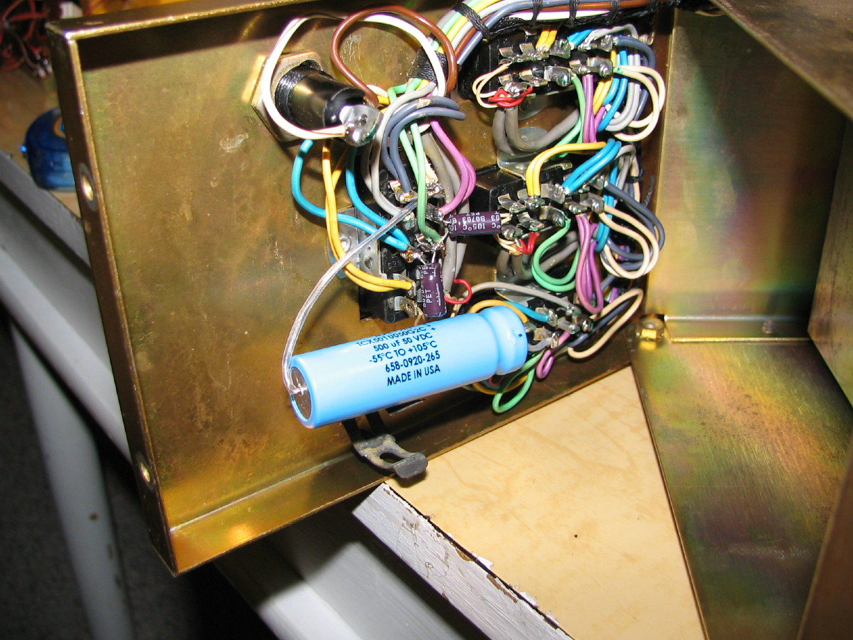
This part was harder than doing the work on the underside because of the tight proximity of all the terminals on the connectors you see there that go to all the electronics modules, and because of the aforementioned winding of component tails around the terminals. In some cases I just clipped and removed everything from a terminal where I had slack and re-stripped wire ends to resolder everything.
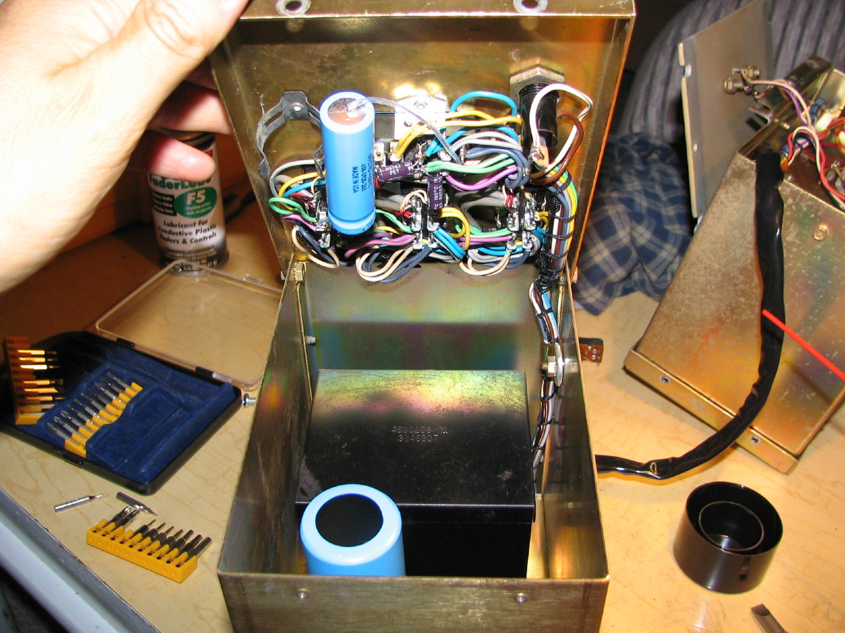
Here is a closing shot with the PSU sitting how it is oriented in the console with the lid open...you can see the top of the big filter cap there along with the new caps on the lid...dusting my hands off and looking ahead to giving the second PSU the same treatment.
Got one of the PSU's rebuilt last night. I tell ya...replacing components that aren't on PCB's requires a little more creativity...there were only 4 caps to replace and I chose to replace the rectifier diodes and bleeder resistor, but it took a good chunk of time last night. On a PCB you can heat and suck the solder and the component is easy to get off, but when the guts aren't on a printed circuit board the tails of the components are wound around terminals and so there is a bit more care, time and attention required to get the old stuff off.
Anyway, I succeeded (though I haven't smoke tested it yet...).
Here is the bottom of the PSU with all the old stuff removed ready for the new stuff to move in...the big hole is where the terminals of the new big filter cap will be, and you can see the three wires that connect to that cap and the terminal strip in background where the diodes will connect:

Filter cap in place along with the recitifier diodes:

And here's the whole mess put back together along with a 0.01uF bypass cap that was recommended. I crimped each bundle on the ring connector and then filled it up with solder. It is kind of fun to do this kind of work because you get to be a little creative with how you route things and lay certain things out...not that I did it the best way...Open to suggestion on that. Tried to keep safety in mind in routing things to avoid the potential for short circuiting. There is a plate that covers most of these components and, again, this is the bottom side of the PSU which gets bolted to a heavy steel shelf which is bolted to the 440 console frame so very stable and protected but...

For contrast here again is the before picture of the same area posted somewhere earlier...

Now to the three caps on the underside of the lid of the PSU...here is the before:

And here is the after:

This part was harder than doing the work on the underside because of the tight proximity of all the terminals on the connectors you see there that go to all the electronics modules, and because of the aforementioned winding of component tails around the terminals. In some cases I just clipped and removed everything from a terminal where I had slack and re-stripped wire ends to resolder everything.
Here is a closing shot with the PSU sitting how it is oriented in the console with the lid open...you can see the top of the big filter cap there along with the new caps on the lid...dusting my hands off and looking ahead to giving the second PSU the same treatment.


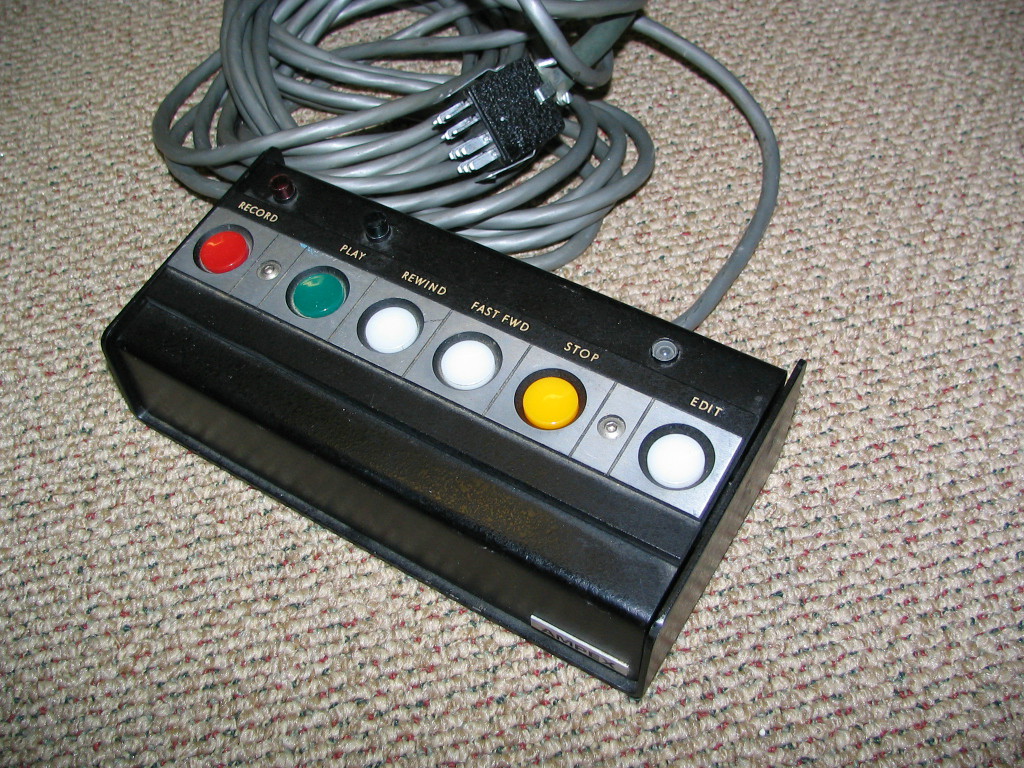

 I had one just like that for my AG-440B 1/4" machine.


 a couple of the folks over at the Ampex List have been invaluable but I don't like to bug them too much.