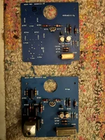
Re filter caps, we ended up leaving the replacements in. He took a esr reading on the og caps and didn't seem enthusiastic with the results. When I saw the machine finally fire up, I figured the replacements are probably ok for now. If I run into issues down the line, I know the mallory caps are a proven route.
I’m sure the replacements are fine…it’s not that they won’t work. It’s that the correct replacements are a much higher-grade part. Professional Ampex machines of this era are not revered for their sophistication. They are revered for their sound. The signal electronics power supply is the life blood of the signal electronics, and the quality of how they filter and slew can be impacted by those primary filter caps. I’m probably splitting hairs, but I would never consider replacing those large can computer-grade caps with standard small-can leaded parts. They’ll work fine. I just wouldn’t choose that for me.
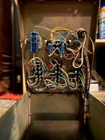
Ya it's odd, there's no corrosion anywhere else on the electronics or machine. The pots and switches are scratchy, I definitely will be getting in there with contact cleaner. The pots look sealed, so not sure if cleaning them is an option unless you know otherwise? The switches look like I can just go in from the front? I'll be exercising everything moveable and removable annnnd if issues still persist, moving down the line once I get the new xlr jacks replaced
What contact cleaner are you planning on using for the switches, and what kind are you planning on using for the pots?
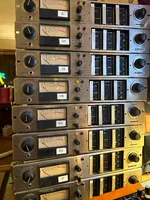
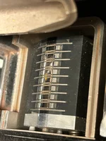
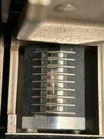
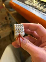
The pots aren’t “sealed” per se, but there isn’t an easy way to get FaderLube in there like with other miniature pots where there might be an access hole. The thing to remember about cleaning pots is it isn’t just about getting cleaner in there, it’s about getting it in there, exercising, and then allowing it to drain, and then flushing and draining. And THAT’S all the quick and dirty way…the BEST way is to open the potentiometer up and actually clean the wiper and element. The pot body on the pots in the AG-440 signal electronics fastens to the element by 4 metal tabs that are wrapped over the back of the element. To remove the body you have to carefully pry up those tabs, straighten them and then just pull the body away, and then go to work cleaning. You want to use the correct type of cleaner, and you want to be gentle, especially with the wiper. This is the only way to really service the pots on the AG-440. I’ve heard of people drilling a small hole in the pot body so there is some access to jet whatever product you are using in there and then allow it to drain. I think this is a TERRIBLE idea…the risk of metal shavings getting in there. I just open them up and do a proper cleaning. Let me know if you need more details.
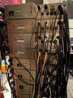
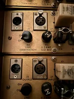
As far as the switches, I don’t know how you would actually ensure the contact cleaner gets to where it needs to go and be able to flush after exercising through the front…yes I suppose on the source select paddle switch, but you’re still not going to be able to see what you’re doing and ensure you are treating all the contacts. The switches are all open-frame type, and the top and bottom covers of the module come off with screws for service access, so there’s no excuse not to just lay a rag towel out, pull the covers off, set the open module on the towel, and actually put the cleaner where it needs to go, exercise, and rinse. And remember the LINE TERMINATION switch on the rear panel. These switches were made in an era when the standard for quality was much higher, and these switches can out-last much of what you will find in contemporary devices, but they certainly can oxidize, and since they are open-frame there is greater potential for infiltration by debris.
Cool! Yes if you get around to it, I def would follow your lead for an alternate incandescent option. Seems simpler than installing led's
Let me be clear, my plan wasn’t drop-in…the only drop-in solution of which I’m aware is if you find original bulbs, and yes they are very hard to find…Sylvania 33217 (“24PC”) 24V bi-pin base lamps. Again I’d have to take some time refreshing my memory on what my plan ended up being, but it was as much work or more than converting to LEDs…modifications to lamp mounting and modifications to the connection and wiring harness. And I chose incandescent because I like the look much better than LEDs, but LEDs are more practical. If I get around to digging up my own archives on this I’ll certainly share here.
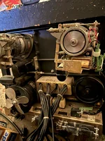
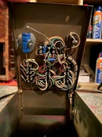
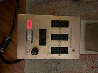
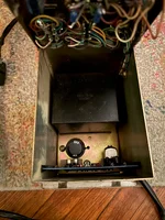
The guys who sold me the deck informed me the pinch roller came from Dave D, so that's a plus. As far as measuring 24v at the pinch roller solenoid, where would I take this reading? Do I need to open up the solenoid to do this? Or open up the control box? Or is there a better place to take get it? There's no visible terminals, just 2 wires coming out of the solenoid going inside of the control box (which I haven't opened yet). The pinch roller isn't moving at all when I press play. I can indeed physically push the pinch roller all the way to the capstan shaft which makes the reels turn.
Okay. It’s been maybe 15 years or more since I’ve had my hands on an AG-440 pinch roller solenoid…my reference is the solenoid on my MM-1000, which is totally different. If it’s not moving at all don’t worry about trying to measure voltage at this point. The solenoids rarely fail, and you’ve got relays on the way. I say get those, install them, and see where you’re at.
Thanks for sending over the mouser link! I just ordered 4 relays
Sure thing. Keep in mind the signal electronics use the same relay for the record relay mounted to the back of the module, so as you get into it, if you’re having issues with tracks not going into record or gremlins moving around with per-track record functionality/intermittency, you might want to consider replacing those 8 relays.
As for the torque delay / power assembly, I'm not holding my breath. I figured I'd ask here as a lot of ampex people have chimed in on this thread over the years. You're correct to wait and see how the machine functions without them. In the back of my head, I've been mulling over the transport getting worn out and tired being used without them. But if it really all just comes down to start up time, I can certainly live with that.
The lack of these things won’t impact the transport life or viability…it might make you tired if it is sluggish.
")
My main concern was whether or not it would work at all without them, but you indicate it does, albeit with bugs to work out. I haven’t looked at AG-440-8 transport schematics in a long, long time, so can’t recall if the system depends on those assemblies, or if they just assist in parallel. I think it’s the former, which means modifications were made to your control box to allow the transport to function without the missing assemblies. So get it working and try it out and see what you think is my advice.
")