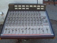
Tascam 388 Story...

So, with your responses I’m pretty sure I know what’s going on, but I want to have you do one more thing before we jump to my hunch. Because you had issues with the solder joints associated with P102, I recommend you reflow the solder joints at P101 on the BUSS B PCB, as well as the associated joints for the corresponding connector on the M BUSS PCB. Do that, and then re-check the STEREO assign functionality; see if it can get signal to propagate from an input channel assigned to the L-R buss to the STEREO OUT jacks and see activity in the STEREO meters. If it works, I’ll explain why, and if it doesn’t work I’ll take us to the next step and explain why I think it will work.
 
So, with your responses I’m pretty sure I know what’s going on, but I want to have you do one more thing before we jump to my hunch. Because you had issues with the solder joints associated with P102, I recommend you reflow the solder joints at P101 on the BUSS B PCB, as well as the associated joints for the corresponding connector on the M BUSS PCB. Do that, and then re-check the STEREO assign functionality; see if it can get signal to propagate from an input channel assigned to the L-R buss to the STEREO OUT jacks and see activity in the STEREO meters. If it works, I’ll explain why, and if it doesn’t work I’ll take us to the next step and explain why I think it will work.
So I did what you asked, reflowed P101 on the buss b pcb and the connector assigned to it on the M buss pcb. Still no sound when I’m on the stereo assign functionality. No activity on the stereo meters also.
 
Okay! SO…I think what we have here is likely what has become a relatively common failure issue with the 388, and the 4069 hex inverter chip U104 on the BUSS B PCB. Why do I think this…all signs point to it based on how we narrowed things down, and based on my experience if things are wonky with signal passing to the STEREO buss upstream of the master fader it’s usually U104.

What does U104 do? Look on page 31 of the manual…you’ll see a chart in the middle of the page that essentially shows the source of the monitor buss when set to STEREO depending on the state of the transport, record electronics and other controls including the L-R assign switches. Well how does that actually work? If you look at the BUSS B PCB schematic on page 4-6 of the service manual, in the middle-ish of the schematic you see a cluster of small triangles. Those represent the guts of U104. If you look at P101 you’ll see pin 9 is labeled STEREO CONT. That carries a control signal up to U104. The power state of the STEREO CONT changes depending on the state of those systems and controls outlined in the chart on page 31. So in simple terms as the state of the control signal changes so do the outputs of U104, and you can follow those up to a series of FET switches Q101, 102, 103 & 104 in the upper right of the drawing. Those are like little switches that are closed or open depending on what U104 tells them to do, and if you trace the sources of those FETs you’ll see two of them source the L & R outputs of the MONITOR mixer, and two of them source the L-R main buss. From the FETs the signal goes on to the input buffer amp of the master STEREO fader as well as the monitor select switch over by the headphone level knob. So you can imagine if U104 is roached the FETs don’t do what they’re supposed to do and a variety of issues happen. The failure state you’re experiencing is one of them…no signal from the L-R buss will pass to the master fader. Some other failure states include no switching of the source and the L-R can always be heard but at a diminished level, or only one side can be heard. If you want to test a couple other things to further verify U104 has failed you’re welcome to do that…reflow solder joints (never experienced failed solder joints here though) and make sure the control signal is making it all the way to pin 14 of U104, for instance. But if it was me I wouldn’t bother because there’s an established trend of the chip failing in the 388 and other period Teac equipment that use that part.

So how did I narrow down to that part, and why did I have you do the tests you did? Well, the symptoms you shared included the main meters not registering signal and no signal present at the STEREO OUT jacks or MONITOR OUT jacks or headphones when STEREO was set as the monitor source, and when any signal was assigned to the L-R buss from an input channel. So I looked at the Block Diagram and just looked at what is in between those outputs and the source…you didn’t indicate there was any problem with the PGM group assign functions, so that told me you had good post-fader signal at the output of the input channels (because the main buss and the PGM groups all get their signal from the same point in the signal path), and you said the problem was global across all input channels, so I made the assumption it wasn’t a problem with one or more input channels themselves or even necessarily the M BUSS PCB (though that still could have been the cause). So that narrowed it to something between the M BUSS PCB and the faulty outputs. So then I had you do a couple things: 1. inject signal to the STEREO BUSS IN jacks and 2. set the monitor source of the headphones and MONITOR OUT jacks to AUX/EFF. The results of #1 was working meters and signal at the STEREO OUT jacks. Look at the Block Diagram again…at the top middle of the drawing you’ll see the STEREO BUSS IN jacks…if you follow the signal path you see signal connected to those input jacks intersects the main buss right upstream of the master fader input buffer amp. So what did that test tell us? That told us there was nothing wrong with your main meters, and that the master fader input buffer amp, master fader and wiring, fader output booster amp and everything else all the way to the STEREO OUT jacks AND the main buss feed to the monitor buss was A-OK. And the results of #2 verified the meters and monitor buss were working. So that narrowed it down to something between the M BUSS PCB and a point upstream of where the STEREO BUSS IN jacks tie in to the main buss. The main buss comes in to the BUSS B PCB at P101. Because you had issues with P102 I thought possibly there was fault there, so reflowing the solder joints there was a just-in-case measure. That made no difference, which leaves the U104 and the FET switches. Based on the symptoms and my experience my educated diagnosis is U104 is faulty, and that’s how I got there.

Through-hole PDIP-14 4069 chips are cheap and readily available. I’m not sure where you are in the world, but Mouser has them.
relatively common failure of the
 
Well, thank you so much
Okay! SO…I think what we have here is likely what has become a relatively common failure issue with the 388, and the 4069 hex inverter chip U104 on the BUSS B PCB. Why do I think this…all signs point to it based on how we narrowed things down, and based on my experience if things are wonky with signal passing to the STEREO buss upstream of the master fader it’s usually U104.

What does U104 do? Look on page 31 of the manual…you’ll see a chart in the middle of the page that essentially shows the source of the monitor buss when set to STEREO depending on the state of the transport, record electronics and other controls including the L-R assign switches. Well how does that actually work? If you look at the BUSS B PCB schematic on page 4-6 of the service manual, in the middle-ish of the schematic you see a cluster of small triangles. Those represent the guts of U104. If you look at P101 you’ll see pin 9 is labeled STEREO CONT. That carries a control signal up to U104. The power state of the STEREO CONT changes depending on the state of those systems and controls outlined in the chart on page 31. So in simple terms as the state of the control signal changes so do the outputs of U104, and you can follow those up to a series of FET switches Q101, 102, 103 & 104 in the upper right of the drawing. Those are like little switches that are closed or open depending on what U104 tells them to do, and if you trace the sources of those FETs you’ll see two of them source the L & R outputs of the MONITOR mixer, and two of them source the L-R main buss. From the FETs the signal goes on to the input buffer amp of the master STEREO fader as well as the monitor select switch over by the headphone level knob. So you can imagine if U104 is roached the FETs don’t do what they’re supposed to do and a variety of issues happen. The failure state you’re experiencing is one of them…no signal from the L-R buss will pass to the master fader. Some other failure states include no switching of the source and the L-R can always be heard but at a diminished level, or only one side can be heard. If you want to test a couple other things to further verify U104 has failed you’re welcome to do that…reflow solder joints (never experienced failed solder joints here though) and make sure the control signal is making it all the way to pin 14 of U104, for instance. But if it was me I wouldn’t bother because there’s an established trend of the chip failing in the 388 and other period Teac equipment that use that part.

So how did I narrow down to that part, and why did I have you do the tests you did? Well, the symptoms you shared included the main meters not registering signal and no signal present at the STEREO OUT jacks or MONITOR OUT jacks or headphones when STEREO was set as the monitor source, and when any signal was assigned to the L-R buss from an input channel. So I looked at the Block Diagram and just looked at what is in between those outputs and the source…you didn’t indicate there was any problem with the PGM group assign functions, so that told me you had good post-fader signal at the output of the input channels (because the main buss and the PGM groups all get their signal from the same point in the signal path), and you said the problem was global across all input channels, so I made the assumption it wasn’t a problem with one or more input channels themselves or even necessarily the M BUSS PCB (though that still could have been the cause). So that narrowed it to something between the M BUSS PCB and the faulty outputs. So then I had you do a couple things: 1. inject signal to the STEREO BUSS IN jacks and 2. set the monitor source of the headphones and MONITOR OUT jacks to AUX/EFF. The results of #1 was working meters and signal at the STEREO OUT jacks. Look at the Block Diagram again…at the top middle of the drawing you’ll see the STEREO BUSS IN jacks…if you follow the signal path you see signal connected to those input jacks intersects the main buss right upstream of the master fader input buffer amp. So what did that test tell us? That told us there was nothing wrong with your main meters, and that the master fader input buffer amp, master fader and wiring, fader output booster amp and everything else all the way to the STEREO OUT jacks AND the main buss feed to the monitor buss was A-OK. And the results of #2 verified the meters and monitor buss were working. So that narrowed it down to something between the M BUSS PCB and a point upstream of where the STEREO BUSS IN jacks tie in to the main buss. The main buss comes in to the BUSS B PCB at P101. Because you had issues with P102 I thought possibly there was fault there, so reflowing the solder joints there was a just-in-case measure. That made no difference, which leaves the U104 and the FET switches. Based on the symptoms and my experience my educated diagnosis is U104 is faulty, and that’s how I got there.

Through-hole PDIP-14 4069 chips are cheap and readily available. I’m not sure where you are in the world, but Mouser has them.
relatively common failure of the
well.. thank you so much for your assistance sweetbeats.

You truly are a master jedi of the tascam 388. If I could shake your hand I would.

When you told me to reflow P101 I took a look at the schematics because it pointed out something was wrong with the path of that connector. I did notice pin 9 which indicated STEREO CONT and following up the path it indeed led to a couple of digital chips.. I suspected that. I trust your judgment, U104 may be the culprit. I had a similar issue in the past with my 388 and got stuck on it for many months, up to a point I almost gave up on it. The motor was behaving very strangely and there was a failure with the rewind and FF functions. Basically the tension arms were not working when pressing these buttons, the pinch roller was not coming off on rewind mode, and other strange behaviours… it was a nightmare. Then one of my friend, an electrical engineer which I wouldnt suspect to be able to help me wirh my issue was kind enough to come and take a look at it. We searched through the entire path for a long time until we finally found out a faulty digital chip (U407 or U408, I can’t remember correctly) on the control pcb; one of the pins was not sending enough voltage. Let me tell you that when I soldered the new chip and experienced a faulty tascam 388 on the verge of being thrown out the window to a functioning machine on the way of getting properly refurbished and calibrated, after so many months of failure, frustrations, a real money pit, I felt proud and relieved of not giving up.

This is one of many problems I encountered but by far was the worst of it all.

I am learning electronics the hard way with this machine. At least it gives me that. Hopefully I’ll finally record my album on it

Thanks to you, hopefully, I will not have to go through the same maddening process.

I had two questions before I end this message.

Firstly, I noticed on the schematics that there is actually three U104 chips. Or is it all the same one? I don’t have the physical PCB in front of the me in the moment. If I am not mistaking it would be really appreciated if you could kindly tell me if I need to replace all of them.

Secondly, this is the product I found on mouser. I would appreciate if you could indicate me if it’s the proper one.

Heres the link:


Thank you for being so instructive and generous of your lnowledge. I respect what you do, it’s very inspiring.


Over to you
 
well.. thank you so much for your assistance sweetbeats.

Well you’re welcome. I wish it was possible to make a living doing this sort of thing because I do enjoy it, and as it stands have extremely little time to engage in it…I don’t even work on my own projects hardly anymore. I’m glad to help. And if my hunch is wrong we’ll keep at it and replacing U104 is good preventative maintenance because if it’s not faulty now, it likely will be in the future.

When you told me to reflow P101 I took a look at the schematics because it pointed out something was wrong with the path of that connector. I did notice pin 9 which indicated STEREO CONT and following up the path it indeed led to a couple of digital chips.. I suspected that. I trust your judgment, U104 may be the culprit. I had a similar issue in the past with my 388 and got stuck on it for many months, up to a point I almost gave up on it. The motor was behaving very strangely and there was a failure with the rewind and FF functions. Basically the tension arms were not working when pressing these buttons, the pinch roller was not coming off on rewind mode, and other strange behaviours… it was a nightmare. Then one of my friend, an electrical engineer which I wouldnt suspect to be able to help me wirh my issue was kind enough to come and take a look at it. We searched through the entire path for a long time until we finally found out a faulty digital chip (U407 or U408, I can’t remember correctly) on the control pcb; one of the pins was not sending enough voltage. Let me tell you that when I soldered the new chip and experienced a faulty tascam 388 on the verge of being thrown out the window to a functioning machine on the way of getting properly refurbished and calibrated, after so many months of failure, frustrations, a real money pit, I felt proud and relieved of not giving up.

Well you seem to have a pretty good grip/instinct for things and don’t seem to be afraid to keep going and trying…and reaching out for help…that is 100% how I’ve learned what I know, the “hard way” I guess. But you’d be surprised just how messed up things have to be before you really have to throw in the towel and I think it comes down to just how much you want the device to work, how much in resources you’re willing to throw at it, how much persistence you’re wired to expend, and many times having the wisdom to, in that moment of complete “Arg!” to know that’s the time to step away for the day or night and know that in 24 hours or whatever you’ll have your composure and motivation again. Sometimes it means having a parts for or machine and just pulling a whole PCB assembly and swapping it in. You should read what I went through trying to get the multi-frequency test tone oscillator working on my early 1980s Tascam prototype console…it’s in my “Tascam M-__ Story…” thread somewhere. Anyway, it wasn’t working, and I had to make it work. I couldn’t stand it being present but not working. I don’t recall ultimately what all had to be done to make it work, but a couple different people helped me learn how the oscillator works and then helped with troubleshooting steps, and it was further complicated because the console is a prototype device and there are no schematics or tech docs. So everything has to be reverse-engineered, so I had to learn how to do that and draw it out. I’m sharing this with you just as perspective to how far things can go if you keep at it. Ultimately it was fixed. You’re friend had good intuitions too with your 388. I’ve found that if a device has IC logic onboard and it’s doing really weird inconsistent things, it often ends up being faulty logic components OR faulty power to the logic. And always start by checking the power source.
Thanks to you, hopefully, I will not have to go through the same maddening process.
Oh it’ll make you mad again…hopefully not now, but at some point. But each time you work on it it becomes more familiar and less intimidating, and remember: in the big picture it’s all progress.
I had two questions before I end this message.


Firstly, I noticed on the schematics that there is actually three U104 chips. Or is it all the same one? I don’t have the physical PCB in front of the me in the moment. If I am not mistaking it would be really appreciated if you could kindly tell me if I need to replace all of them.
No there’s just one…it’s a little confusing how the part is represented on the drawing…they’ve just deconstructed the circuit that’s housed in the chip because that’s how the schematic is drawn. Typically there would be some sort of section identifier, like instead of what looks like three separate components each labeled “U104, U104, U104”, it would be labeled as “U104-1, U104-2, U104-3”; three sections of one component, or something like that. Because, anyway, you would never have the same component identifier used three times. Each component has, or *should* have its own separate identifier. You can see what I’m talking about right next to U104 on the schematic just to the right with the PGM 1 input amp and fader booster U301…it’s a TL072 dual opamp, so two opamps in one chip, one side does the input stage ahead of the fader and the other side does the post fader booster amp. It’s one part, U301, but in this case they label it as “U301 (1/2)” and “U301 (2/2)”. So anyway, there is just one U104. BUT…verify the part by looking at the physical assembly! I am almost certain from memory it is a 4069, but the parts list notes a 4049. The 388 manual is particularly riddled with errors, so I think the parts list is in error, but just look at the physical part to verify before you buy.
Secondly, this is the product I found on mouser. I would appreciate if you could indicate me if it’s the proper one.


Heres the link:


https://www.mouser.ca/ProductDetail/Texas-Instruments/CD4069UBE?qs=gqbMQSs93zN4MVMbMFTI6g==
Yes that’s exactly it. Assuming you verify as above by looking at the physical assembly and it is indeed a 4069. I’m 99.9% sure that’s what you’ll find and that part at Mouser is the one I would pick. I tend to use TI parts when available, and except in rare circumstances only buy from a reputable retailer like Mouser, Digikey, Newark, Allied Electronics, etc…all your problems (hopefully) solved for $0.89USD plus shipping. Pretty amazing really. I have a decent collection of through-hole parts. Over time they will become harder and more expensive to find.
Okay. Your turn.
 
Well you’re welcome. I wish it was possible to make a living doing this sort of thing because I do enjoy it, and as it stands have extremely little time to engage in it…I don’t even work on my own projects hardly anymore. I’m glad to help. And if my hunch is wrong we’ll keep at it and replacing U104 is good preventative maintenance because if it’s not faulty now, it likely will be in the future.


Well you seem to have a pretty good grip/instinct for things and don’t seem to be afraid to keep going and trying…and reaching out for help…that is 100% how I’ve learned what I know, the “hard way” I guess. But you’d be surprised just how messed up things have to be before you really have to throw in the towel and I think it comes down to just how much you want the device to work, how much in resources you’re willing to throw at it, how much persistence you’re wired to expend, and many times having the wisdom to, in that moment of complete “Arg!” to know that’s the time to step away for the day or night and know that in 24 hours or whatever you’ll have your composure and motivation again. Sometimes it means having a parts for or machine and just pulling a whole PCB assembly and swapping it in. You should read what I went through trying to get the multi-frequency test tone oscillator working on my early 1980s Tascam prototype console…it’s in my “Tascam M-__ Story…” thread somewhere. Anyway, it wasn’t working, and I had to make it work. I couldn’t stand it being present but not working. I don’t recall ultimately what all had to be done to make it work, but a couple different people helped me learn how the oscillator works and then helped with troubleshooting steps, and it was further complicated because the console is a prototype device and there are no schematics or tech docs. So everything has to be reverse-engineered, so I had to learn how to do that and draw it out. I’m sharing this with you just as perspective to how far things can go if you keep at it. Ultimately it was fixed. You’re friend had good intuitions too with your 388. I’ve found that if a device has IC logic onboard and it’s doing really weird inconsistent things, it often ends up being faulty logic components OR faulty power to the logic. And always start by checking the power source.

Oh it’ll make you mad again…hopefully not now, but at some point. But each time you work on it it becomes more familiar and less intimidating, and remember: in the big picture it’s all progress.

No there’s just one…it’s a little confusing how the part is represented on the drawing…they’ve just deconstructed the circuit that’s housed in the chip because that’s how the schematic is drawn. Typically there would be some sort of section identifier, like instead of what looks like three separate components each labeled “U104, U104, U104”, it would be labeled as “U104-1, U104-2, U104-3”; three sections of one component, or something like that. Because, anyway, you would never have the same component identifier used three times. Each component has, or *should* have its own separate identifier. You can see what I’m talking about right next to U104 on the schematic just to the right with the PGM 1 input amp and fader booster U301…it’s a TL072 dual opamp, so two opamps in one chip, one side does the input stage ahead of the fader and the other side does the post fader booster amp. It’s one part, U301, but in this case they label it as “U301 (1/2)” and “U301 (2/2)”. So anyway, there is just one U104. BUT…verify the part by looking at the physical assembly! I am almost certain from memory it is a 4069, but the parts list notes a 4049. The 388 manual is particularly riddled with errors, so I think the parts list is in error, but just look at the physical part to verify before you buy.

Yes that’s exactly it. Assuming you verify as above by looking at the physical assembly and it is indeed a 4069. I’m 99.9% sure that’s what you’ll find and that part at Mouser is the one I would pick. I tend to use TI parts when available, and except in rare circumstances only buy from a reputable retailer like Mouser, Digikey, Newark, Allied Electronics, etc…all your problems (hopefully) solved for $0.89USD plus shipping. Pretty amazing really. I have a decent collection of through-hole parts. Over time they will become harder and more expensive to find.
Okay. Your turn.
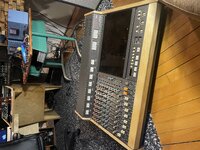
Hey!


So I have ordered and replaced the chip. And… it works!


All thanks to you. I really appreciate it!

Here is a picture of my tascam.. I did custom pannels with cherry tree so it can match my studio desk in my studio.

I recorded a couple of stuffs alrwady on it, it’s amazing how good it sounds.. gotta be careful with the peak and distortion though. I noticed that as soon as I hit it too hard the deck will distort in the low end but not in a good way. Just need to gain stage properly.
My calibration helps a lot. It’s crazy how the fidelity have improved since the first time I used it. I was used to make it peak all the time.. it was the only way to get a proper volume wothout too much hiss. Ot wouldnt distort so much. but now when the tascam says peak, it actually peaks for real. lol.

There is a strange thing that happens though when I lean on the edge of the deck with too much weight.. it kind of shut down for a second or the power kind of drops, the intensity of the leds jn the vu meter drops a little bit, I also notice peak leds flashing red, the information on the counter display disappears and reappears.. really strange. But it comes back as soon as I release the weight. I noticed that as I was working on a recording.

Do you think it might be the control pcb which is right underneath the "elbow seat" touching some metal because of the weight and creating some kind of short circuit..?


I also noticed another issue.

The gain knob of channel 7 on the buss section is intermittent, it’ll only work if the gain is pushed all the way. Otherwise there is no sound on channel 7. And the gain knob of channel 8 behaves badly too, the volume will not shut down when I shut it down. Maybe a connector cable? I messed around a lot in that area lately with the past issue.


anyways, it’s alive. And it works pretty well. This is fine tuning. Let me know your thoughts on these matters when you get a minute!

Merry Christmas
 

Attachments

  • 12571322-AF94-46E9-8F44-B95737F26362.jpeg
    12571322-AF94-46E9-8F44-B95737F26362.jpeg
    3.8 MB · Views: 4
So I have ordered and replaced the chip. And… it works!
Fantastic. I love that. Doesn’t that feel good? Good job.

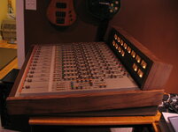
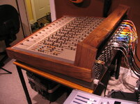
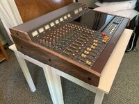
Here is a picture of my tascam.. I did custom pannels with cherry tree so it can match my studio desk in my studio.


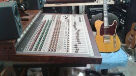
Oh that looks good. Yeah I like the fact a lot of the vintage Teac consoles have relatively simple panels to reproduce if you want to upgrade to hardwood. I did that with my prototype “M-__” console, which was pretty trashed when I acquired it…I used hybrid black/English walnut harvested from a dead tree we had to fell where I used to live…had the log chunks rough cut and I planed planks and cut to size. Here’s before and after pics:

07219EF3-BFF5-457C-8F4E-80466D32BDCD.jpeg

F62C83BC-CAC9-44CD-B98C-A16E82E5166C.jpeg

D666B2A0-BCA6-4E01-86D2-79B9D011E8FB.jpeg

I recorded a couple of stuffs alrwady on it, it’s amazing how good it sounds.. gotta be careful with the peak and distortion though. I noticed that as soon as I hit it too hard the deck will distort in the low end but not in a good way. Just need to gain stage properly.

Right. Yeah that’s a good observation…that was my experience too. I know there’s a whole lot of lore about either something like the 388 being “lo-fi” and/or people thinking it’s awesome to “slam the tape”, but if it’s setup right and you’re using the dbx the noise floor is really well-managed, if you slam it you throw the dbx tracking off, if you turn that off to avoid that and hit it hard you’re probably distorting the amplifier electronics and not the tape…set it up correctly and you get a surprisingly smooth gluey and low noise analog recording. But the setup is critical to that and bias in particular since the tape that’s available new is not from the Ampex/Quantegy lineage and the bias requirements are significantly different, and the 388 service manual assumes you are using 457.

There is a strange thing that happens though when I lean on the edge of the deck with too much weight.. it kind of shut down for a second or the power kind of drops, the intensity of the leds jn the vu meter drops a little bit, I also notice peak leds flashing red, the information on the counter display disappears and reappears.. really strange. But it comes back as soon as I release the weight. I noticed that as I was working on a recording.
Are you talking about if you lean on the wrist rest? And if that’s what you mean does it happen if you press down anywhere on the wrist rest or is it only toward the right side?

Do you think it might be the control pcb which is right underneath the "elbow seat" touching some metal because of the weight and creating some kind of short circuit..?

Yeah I’m thinking you may have a pinched wire are something is making contact that shouldn’t be when there’s that pressure. Clarify for me though where you can press to make it happen. And have you removed or ever done any disassembly of the guts that are under the transport and monitor control panels there between the transport and the wrist rest? You’re correct the control PCB is there and also the monitor amp assembly…wires…guts…

I also noticed another issue.
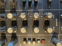
The gain knob of channel 7 on the buss section is intermittent, it’ll only work if the gain is pushed all the way. Otherwise there is no sound on channel 7. And the gain knob of channel 8 behaves badly too, the volume will not shut down when I shut it down. Maybe a connector cable? I messed around a lot in that area lately with the past issue.

Are you talking about the level controls for channels 7 and 8 in the monitor section? The 8 channels of pan and level knobs above the PGM MASTER faders?
 
Last edited:
Fantastic. I love that. Doesn’t that feel good? Good job.
It does feel amazing.
Here is a picture of my tascam.. I did custom pannels with cherry tree so it can match my studio desk in my studio.

Oh that looks good. Yeah I like the fact a lot of the vintage Teac consoles have relatively simple panels to reproduce if you want to upgrade to hardwood. I did that with my prototype “M-__” console, which was pretty trashed when I acquired it…I used hybrid black/English walnut harvested from a dead tree we had to fell where I used to live…had the log chunks rough cut and I planed planks and cut to size. Here’s before and after pics:

View attachment 124268

View attachment 124271

View attachment 124274

I recorded a couple of stuffs alrwady on it, it’s amazing how good it sounds.. gotta be careful with the peak and distortion though. I noticed that as soon as I hit it too hard the deck will distort in the low end but not in a good way. Just need to gain stage properly.

Right. Yeah that’s a good observation…that was my experience too. I know there’s a whole lot of lore about either something like the 388 being “lo-fi” and/or people thinking it’s awesome to “slam the tape”, but if it’s setup right and you’re using the dbx the noise floor is really well-managed, if you slam it you throw the dbx tracking off, if you turn that off to avoid that and hit it hard you’re probably distorting the amplifier electronics and not the tape…set it up correctly and you get a surprisingly smooth gluey and low noise analog recording. But the setup is critical to that and bias in particular since the tape that’s available new is not from the Ampex/Quantegy lineage and the bias requirements are significantly different, and the 388 service manual assumes you are using 457.

There is a strange thing that happens though when I lean on the edge of the deck with too much weight.. it kind of shut down for a second or the power kind of drops, the intensity of the leds jn the vu meter drops a little bit, I also notice peak leds flashing red, the information on the counter display disappears and reappears.. really strange. But it comes back as soon as I release the weight. I noticed that as I was working on a recording.
Are you talking about if you lean on the wrist rest? And if that’s what you mean does it happen if you press down anywhere on the wrist rest or is it only toward the right side?

Do you think it might be the control pcb which is right underneath the "elbow seat" touching some metal because of the weight and creating some kind of short circuit..?

Yeah I’m thinking you may have a pinched wire are something is making contact that shouldn’t be when there’s that pressure. Clarify for me though where you can press to make it happen. And have you removed or ever done any disassembly of the guts that are under the transport and monitor control panels there between the transport and the wrist rest? You’re correct the control PCB is there and also the monitor amp assembly…wires…guts…

I also noticed another issue.


Are you talking about the level controls for channels 7 and 8 in the monitor section? The 8 channels of pan and level knobs above the PGM MASTER faders
Fantastic. I love that. Doesn’t that feel good? Good job.

Here is a picture of my tascam.. I did custom pannels with cherry tree so it can match my studio desk in my studio.

Oh that looks good. Yeah I like the fact a lot of the vintage Teac consoles have relatively simple panels to reproduce if you want to upgrade to hardwood. I did that with my prototype “M-__” console, which was pretty trashed when I acquired it…I used hybrid black/English walnut harvested from a dead tree we had to fell where I used to live…had the log chunks rough cut and I planed planks and cut to size. Here’s before and after pics:

View attachment 124268

View attachment 124271

View attachment 124274

I recorded a couple of stuffs alrwady on it, it’s amazing how good it sounds.. gotta be careful with the peak and distortion though. I noticed that as soon as I hit it too hard the deck will distort in the low end but not in a good way. Just need to gain stage properly.
Wow. Beautiful job on your teac board. Such a beaut.
Right. Yeah that’s a good observation…that was my experience too. I know there’s a whole lot of lore about either something like the 388 being “lo-fi” and/or people thinking it’s awesome to “slam the tape”, but if it’s setup right and you’re using the dbx the noise floor is really well-managed, if you slam it you throw the dbx tracking off, if you turn that off to avoid that and hit it hard you’re probably distorting the amplifier electronics and not the tape…set it up correctly and you get a surprisingly smooth gluey and low noise analog recording. But the setup is critical to that and bias in particular since the tape that’s available new is not from the Ampex/Quantegy lineage and the bias requirements are significantly different, and the 388 service manual assumes you are using 457.

There is a strange thing that happens though when I lean on the edge of the deck with too much weight.. it kind of shut down for a second or the power kind of drops, the intensity of the leds jn the vu meter drops a little bit, I also notice peak leds flashing red, the information on the counter display disappears and reappears.. really strange. But it comes back as soon as I release the weight. I noticed that as I was working on a recording.
Are you talking about if you lean on the wrist rest? And if that’s what you mean does it happen if you press down anywhere on the wrist rest or is it only toward the right side?

Do you think it might be the control pcb which is right underneath the "elbow seat" touching some metal because of the weight and creating some kind of short circuit..?

Yeah I’m thinking you may have a pinched wire are something is making contact that shouldn’t be when there’s that pressure. Clarify for me though where you can press to make it happen. And have you removed or ever done any disassembly of the guts that are under the transport and monitor control panels there between the transport and the wrist rest? You’re correct the control PCB is there and also the monitor amp assembly…wires…guts…
I also noticed another issue.


Are you talking about the level controls for channels 7 and 8 in the monitor section? The 8 channels of pan and level knobs above the PGM MASTER faders?
Yes, I’m talking about the wrist rest. It happens no matter where I press against it.
Here is a video I uploaded of the issue:


EDIT: yes I did deassemble the control pcb at two times, one when I had to change the chip on it but it never did thst thing after, and then when I had to replace the wrist rest which was done recently.

Yes I am talking about the volume knobs above the pgm master faders! The section on the photo I attached. I use it a lot during tracking as monitoring and I record my clic on track 8 and it’s inconvenient to not be able to turn up or down the volume of that clic.


Thanks!
 

Attachments

  • E70ACBB5-7C0C-4C91-A9CD-D8F6E41E4B61.jpeg
    E70ACBB5-7C0C-4C91-A9CD-D8F6E41E4B61.jpeg
    3.5 MB · Views: 0
Last edited:
On the monitor mixer channel 7 & 8 issue, am I correct it doesn’t matter if the monitor mixer source is tape tracks 7 & 8 or PGM groups 7 & 8 right? Identical performance problem with either source?

And with the wrist rest issue, I think if it was me I would tip the unit on its side, make sure it’s stabilized somehow, and gently push in different areas of the bottom panel with the unit powered up to see if pushing on the bottom panel causes the same issue. If it does I’d note where it does, remove the bottom panel and look for pinched wires, damaged PCB assembly, that sort of thing. If it *doesn’t* cause the issue by pushing on the bottom panel I’d still do the same thing as above…pull the panel and have a look. The step with pushing on the bottom panel is just a measure that might help you narrow in locationally. If there is nothing conclusive with any of the above, with the bottom panel off I would start probing, gently manipulating PCBs, wire harness sections to try and reproduce the issue. That’s my suggestion. Be aware that doing any of this could cause further damage. We don’t know what’s wrong and the 388 is complex with how power snakes through the unit and is shared. You can always pull the bottom panel with the unit unplugged and look first to see if you see anything obvious too. That might be a better first step, but if something is shorting on the bottom panel, removing the panel will make it impossible to reproduce the problem and isolate where it originates.
Holy Crap......having been an electronic technician for a worldwide Japanese company for many years......and having had a 388 many years ago too......I began to follow this thread just because it was so interesting! But WOW!!! What a genius we have here in SWEETBEATS!!!! I mean.......I would need 5 more lifetimes in audio deck electronics to learn HALF of what he knows!

Cudos!!

Mick
 
I made new black walnut side panels for my 388
A0A56EA8-1631-4D73-9C57-05893BAA484E.jpeg

The only things that appear to be wrong with my unit is a dent on the front arm rest that I think corresponds with the broken “glass” front of #7 VU meter. The meter still works and lights, it’s just missing the plastic lens. I have a replacement set of 4 VUs but havent installed them yet or opened the unit to bang the dent out of the arm rest and recover it. For now, i’ve just left it alone since it all works!

Yours is looking great and there is NO ONE hear that knows more about these old Tascam units than the genius that is @sweetbeats!!! We are so lucky to have him here!
 
I made new black walnut side panels for my 388
View attachment 124316

The only things that appear to be wrong with my unit is a dent on the front arm rest that I think corresponds with the broken “glass” front of #7 VU meter. The meter still works and lights, it’s just missing the plastic lens. I have a replacement set of 4 VUs but havent installed them yet or opened the unit to bang the dent out of the arm rest and recover it. For now, i’ve just left it alone since it all works!

Yours is looking great and there is NO ONE hear that knows more about these old Tascam units than the genius that is @sweetbeats!!! We are so lucky to have him here!
Nice. I made black walnut panels for my M520 as well.
25C1C698-AD8B-4F01-92A1-8989202F0A7E.jpeg
 
Nice! if I hadn’t removed mine to put it in my console desk, I was going to make black walnut ones for the 520 as well! Looks great and I love the way you combined the meter bridge
 
  • Like
Reactions: RFR
Holy Crap......having been an electronic technician for a worldwide Japanese company for many years......and having had a 388 many years ago too......I began to follow this thread just because it was so interesting! But WOW!!! What a genius we have here in SWEETBEATS!!!! I mean.......I would need 5 more lifetimes in audio deck electronics to learn HALF of what he knows!

Cudos!!

Mick
Dude that is way kind…what everybody needs to realize is that I have people way smarter than me that I reach out to, and that my scope of expertise is focused on certain tape machines and analog mixers. But I do like to study schematics and I have put my hands in a wide variety of devices…have a curious mind etc, and do like to help people when I can. But thanks for the kudos. I do appreciate that. I’m sure the reality is your tech chops are better than mine. And I do want to give credit to all the people that, right here on this forum and in other venues, helped me learn. Just search my threads here and you’ll see I started as a greenhorn newbie and I’m still learning every day, and each time I help somebody else.
 
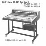
@RFR and @flyingace you guys are killing it with your custom panels. Looks nice. @RFR that reminds me of the factory “top board” option for the M-500 on yours, but yours is surely nicer being hardwood, etc.

View attachment 124322
Thanks!
And not to toot my own horn ( but I’ll do it anyway :LOL: )

Factory one looks clunky. Mine in addition to being made from nice lumber, is visually sleeker.
@flyingace yours is awesome too. (y)
 
My 388 sits well in the center of my
home studio. I have had it since the
80’s and we have hard well together!
 

Attachments

  • 9A194AA3-C351-490E-B36F-28A2E318F081.jpeg
    9A194AA3-C351-490E-B36F-28A2E318F081.jpeg
    2.4 MB · Views: 8
  • Like
Reactions: RFR
On the monitor mixer channel 7 & 8 issue, am I correct it doesn’t matter if the monitor mixer source is tape tracks 7 & 8 or PGM groups 7 & 8 right? Identical performance problem with either source?
I respectfully have to say I don’t follow you a 100% on this one, if I can be more clear, when all the L/R switches on every channels are unpressed the machine switches to monitor sub mix section. This is where the trouble happens with channel 7 and 8. But if L\R switches are engaged (the monitor submix section being bypassed) everything works fine. It’s the gain knob of channel 7 and 8 on the monitor submix that are faulty. Hope it clarifies that.
And with the wrist rest issue, I think if it was me I would tip the unit on its side, make sure it’s stabilized somehow, and gently push in different areas of the bottom panel with the unit powered up to see if pushing on the bottom panel causes the same issue. If it does I’d note where it does, remove the bottom panel and look for pinched wires, damaged PCB assembly, that sort of thing. If it *doesn’t* cause the issue by pushing on the bottom panel I’d still do the same thing as above…pull the panel and have a look. The step with pushing on the bottom panel is just a measure that might help you narrow in locationally. If there is nothing conclusive with any of the above, with the bottom panel off I would start probing, gently manipulating PCBs, wire harness sections to try and reproduce the issue. That’s my suggestion. Be aware that doing any of this could cause further damage. We don’t know what’s wrong and the 388 is complex with how power snakes through the unit and is shared. You can always pull the bottom panel with the unit unplugged and look first to see if you see anything obvious too. That might be a better first step, but if something is shorting on the bottom panel, removing the panel will make it impossible to reproduce the problem and isolate where it originates.

I get that! Gotta be super careful with that kind of things. I was wondering if it would be a good idea to put electrical tape all over the inside of the bottom pannel so that it would prevent any kind of touching to any components/ PCBs. Also just gotta pop the trunk and see if everything is tight in there, nothing loose.
 
Back
Top