Good idea- let's do a simplified example (although this stuff never really gets _simple_!). I don't know what board you have, so for the purposes of discussion, let's assume it is something like a Mackie 1604: 16 mic pres, 16 separate line ins, direct outs on channels 1-8, 4 submix outs, a master stereo pair out, and a control room monitor section that lets you monitor either the main stereo mix or the "tape return" stereo pair. For the moment, let's just ignore the aux sends and returns.
I'm not that familiar with the Darla, but it looks like it has 8 line ins and 10 line outs- the extra two presumably being for monitoring a stereo pair. Cool.
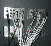
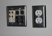
With this rig, I'd start with 3 52-point Switchcraft telephone-style patch strips: 156 points will certainly get you going. We won't use them all in this example, but I'm recommending getting at least that many for expansion room. Each strip will give you two rows of 26 jacks, or 26 jack pairs: an output on the upper, and an input on the lower.
Let's take the basic line-level setup, one channel at a time. Because the Mackie is not an inline-monitor board, I'd probably do a default setup with 8 channels dedicated to input (the board is designed for this, with the direct outs on 1-8), and 8 to monitoring the Darla's 8 tracks: treating it like a good old 8-track tape machine, and ignoring its internal mix/monitor capabilities for this example. You may choose to do this differently, of course, but that'd be my normal setup. Let's call board channels 1-8 the "input" channels, and 9-16 the "monitor" channels (you can always override this later by repatching- don't panic!).
On the top patch strip, I'd run the direct out on board channel 1 to the top jack of the first pair, and the line in 1 on the Darla to the bottom jack. I'd then set up that jack pair as half-normal (tip on the top to tip-switched on the bottom, and the same for ring). That way, with no patch cord in place, the board's direct out 1 is normalled: connected straight into the Darla's input 1. I'd do the same thing for the next 7 jack pairs, until I had direct out 1-8 normalled to Darla in 1-8.
I'd then go down to the next patch strip. On the first 16 bottom jacks, I'd put line inputs 1-16, in order. I'd leave the top jacks for 1-8 unused for the time being, and then on the top jacks for 9-16 I would put the Darla's line out 1-8. I would then half-normal Darla out 1 to line in 9, and so on up to Darla out 8/line in 16. This way, with no patch cables in, the Darla outputs will show up on the board's line inputs 9-16 by default. And you're ready to track: run your inputs into 1-8, do a monitor mix with 9-16, everybody's happy, and there's not a single patch cable in place: the normalling does the connections for you. But you can still repatch anything to anything else: all signals are right there for your use.
Let's make it more interesting. Still on the second strip, let's put the Darla's output 9-10 on two top jacks, say right next to its 1-8 outputs. Then, on the corresponding bottom jacks, connect the mixer's "tape monitor in" left and right, and half-normal them. This creates a default route from the Darla's internal stereo mix back to your monitoring section in the board: you're basically making 9-10 into a 2-track deck. And what the heck: right beside those, run the "control room out" left and right from the board to a set of upper jacks, and the monitor power amp left and right inputs to the corresponding jacks right below, and half-normal them. This creates a default route from your board's monitor section to the monitor amp. See where I'm going with this? Everything comes in to the patch bay, and the normalling routes it to where you want it to go, by default.
Finally, on the third strip, I'd do 16 insert pairs. You'd run a single cable from each pair of jacks back to the corresponding channel insert on the board, essentially "extending" them all to the patchbay. Connect ring on the insert to tip on the upper (output) jack, tip on the insert to tip on the _lower_ (return) jack, and then half-normal them. Connect ring on both the upper and lower *jacks* to ground via 600-ohm resistors, making a pseudo-impedance-balanced connection out of the basically single-ended inserts. That'll give you best noise performance when patching balanced gear onto the inserts. You certainly can just short the ring to ground, and it will work, but this is Art, and I'm a well-known turd-polisher. Anyway, when nothing is plugged in, insert out is routed right back to insert return: just as if nothing was plugged into the insert jack at the board at all.
However, the inserts are now set up for a slick thing: because they are half-normalled, you can use them as direct outs. Stick a cable in the upper jack, and you can steal the signal from a channel without breaking the normal insert-to-return path. Ditto with a direct out, or a Darla out: Plugging into the *output* side of a half-normal pair does not disturb the default route, and gives you maximum flexibility.
With all this half-normalling, you can always override the normal connection to an input: you could take Darla output 9, for example, which is normally tape monitor input L the way we set it up above, and stick it into line input 9. That would *replace* Darla out 1 (which is normally there) with Darla out 9: patching to the *input* side of a half-normal pair breaks the normal. Or, if you put your 4 submix outs on some top jacks somewhere, you could grab submix 1 out and patch it into Darla input 7, for example- for bouncing, or just tracking a mix.
Another example: you can record a guitar track direct in, clean and dry, on track 1- by simply plugging a mic into channel 1 on the board. And if you wanted to play around some, you could steal channel 1's insert out, run it off to a reverb or a Pod or whatever, and then route it back to Darla input 2: viola', clean guitar on track 1, dirty on 2, and only 2 patch cables used.
The point being that you _can_ do all this exception-making stuff, but you don't _have_ to: pull out all the patch cables, and you're normalled up and ready to track.
Inline-monitor boards (like the Alesis Studio 32, or the Soundcraft Ghost) are much nicer for complex recording setups, because they provide a separate set of tape monitor inputs. This allows you to do multitrack monitor mixes *without using up your main line inputs*. If you have an inline board, you'd change the example above to use them- which would leave all 16 line ins for input use at all times. It is awkward, but still very doable, to do multitrack recording with a straight board, but it gives me hives because of all the repatching. You may well end up doing essentially all your monitor mixing in the computer, and just outputting a stereo pair back to the board- who knows? Develop a working style, and then heat up that soldering iron!
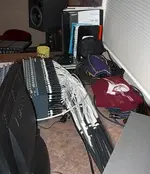
So much for line ins. You'll probably find that you use the same mic lines to the same locations for almost every tracking session- so those, I'd just hard-patch from the wall to the mic ins on maybe 4-5 channels. The other mic ins I'd run to an XLR patchbay so you can redo them without crawling behind the board. The mic patching is going to be very style-dependent, though.
The bottom line is that with a non-inline board, you'll be doing much more repatching than with an inline board, and monitor mixes (the bane of my existence!) are more of a chore- or reduce the number of available inputs...
Lotsa words. Hope that helps a little bit, anyway.
") ... but I'm fighting to get to 250+ posts so I can stop. Instant plastic surgery
... but I'm fighting to get to 250+ posts so I can stop. Instant plastic surgery 