Studio Cabling

  • Thread starter Thread starter frederic
  • Start date Start date
Brian,

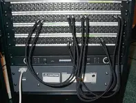
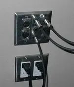
For audio connections, patch bays are your friend, whether soldered or not soldered. With most patch bays, the top row of jacks are "normalled" to the bottom row of jacks, thus if you do not patch anything on the front of the patchbay, the connection top to bottom is passed through. Instruments, outboard and synthesizers across the top row, and the bottom row connected to your mixing console. Then as you need to remove connections from say, channel five on your console and plug your guitar in, you just plug the guitar into the bottom jack associated with Mixer channel five :)

You can hardwire the patch bays (like I and others have done), or purchase a patch bay that has 1/4" jacks front and back, thus using regular patch cords to make wiring easy.

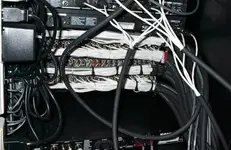
Its been said here (and other places I have asked) that terminal strips and punchdown blocks reduce the signal quality, whereas soldered patchbays do not (at least not as bad, any connection reduces signal quality because of dissimilar metals touching) and at this point I cannot say if I'm convinced or not that punchdown blocks/terminal strips would or would not be a good idea. The logic is that the ends of the cables are exposed, and "squished" into a connector rather than soldered and therefore reduces the quality of the signal. I do agree with this completely.

However, a lot of ADC patch bays can be purchased with punchdown connections on the back, rather than solder the wires. Interesting? I think so :) Punchdown blocks are used in studios all the time, as are soldered connections.

*sigh*

This stuff can never be truly easy :)

Frederic


Brian Grey said:
Ok,

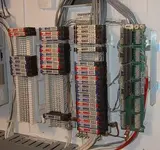
I think I'm finally getting an idea of what a patchbay actually does, and it was what I thought it was originally. In my field I do very similar things, using a terminal strip. If I've got a cabinet full of electrical equipment, I wire each device into a terminal strip. A terminal strip consists of terminal blocks, which is nothing more than... on one side of it a wire comes in, you tighten a screw down on it, and on the other end of the block you put another wire and tighten that screw down. So that way I can have each device hard wired to the terminal strip, but not actually going anywhere yet. Then I can use the device as I need without having to deal with the wires that go to that device, I Just wire into the terminal strip, which is labled clearly.

Now I have to think about how I'm going to do this in my studio...
 
Ahh da da da... You got a bit confused about what I was saying... I was talking about terminal strips because I'm an electronics technician. I'm the wiring I do at work I use terminal strips, for PLC's, variable frequency drives, amplifiers, etc... I wasn't talking about using terminal strips for audio use, I was simply associating terminal strips to a patchbay, as being the same theory.
 
Here's the additional info I promised on normalling and multing. Patchbay jacks are 5-terminal devices: you have the tip, ring, and sleeve contacts for the plug. Additionally, you also have two *switch* contacts: tip-switched and ring-switched. When you insert a plug in the jack, the tip and ring contacts "bend back" away from the tip-switched and ring-switched contacts as the plug is seated: the connection between tip and tip-switched, and ring and ring-switched, is broken by the action of inserting the plug. It works just like relay contacts: it is in fact a mechanical relay.

Normalling works as follows. Studio patch points are usually implemented with pairs of jacks: the upper jack, by normal convention, is a signal source (an output of something). The lower jack is a signal destination (an input of something). Given a pair of jacks, you can have four possible nomalling arrangements: open, full-normal, half-normal, and parallel.

Open, or non-normalled: the upper and lower jacks are completely independent. They don't talk to one another at all by default, so to establish signal flow, you have to plug a patch cable from one to the other. This is what a lot of people think patchbays are full of, but it isn't the most useful arrangement. Using normalling to set up a default signal route is the big win.

Full normal: There is a default ("normal") connection made between the upper and lower jacks of a pair: tip-switched on the upper is connected to tip-switched on the lower, and the same for ring. Sleeve is just connected together non-switched. Thus, this jack pair will default to being connected whenever there is nothing plugged into *either one of them*. Sticking a plug in the upper disconnects the default signal route from the lower ("breaking the normal"), so you have to run another patch cord into the lower from somewhere if you want that destination to be driven. Ditto with sticking a plug in the lower. Important point: a plug inserted in *either* jack of the pair will break the normal.

Half normal: this is IMHO the most useful type. There is a default connection from upper to lower, just like the full normal. However, it is set up so that plugging into the upper (source) jack _does not break it_. To do this, you connect tip on the upper to tip-switched on the lower, and the same for ring. Once again, sleeve is just connected non-switched. This provides you the ability to parallel two loads on a single source: plug a patch into the upper, and pick off the signal to run somewhere else- and it also still goes to the default destination (i.e., a freebie two-way mult, since both your patch and the default destination are driven). Important point 2: *Only* plugging into the lower jack breaks the normal.

Parallel: the jacks are connected without any normal switching (they are hard-shorted in parallel tip-to-tip, ring-to-ring, and sleeve-to-sleeve, whether anything is stuck in them or not). This is also called multing, because it is used to allow an output to drive multiple inputs (within reason, of course). I usually put 3 or 4 4-way mults into any patchbay I build. Mults typically run horizontally, since in the old Switchcraft telephone style patch bays the solder lugs all line up, so you can just stick pieces of tinned wire straight along and glom 'em together.

Hey, sjoko2- thanks for the links! The best page for getting your arms around these normalling contacts is
http://www.patchbays.com/norm_ground.htm
Gotta add that to my bookmarks- it'll save some typing next time...

The more "modern" prepackaged TRS patchbays (simple 1/4" TRS jacks on the front and back) made with PC board mount jacks can be a little harder to do mults with. No problem for me, since I don't use 'em. I'm a throwback: I like the old telephone-style longframes, because I've never yet had one fail unless it was _mercilessly_ abused. And the Switchcraft telephone style patch cords cost $20 a pop because they are the next best thing to immortal...

Just about the only thing that will kill a longframe jack is sticking a regular (stereo-headphone-type) 1/4" TRS plug in it too many times. The real telephone-style TRS plugs have that funny empty-condom tip shape to keep from overstressing the spring contacts that do the normalling for you. I always build a single space rack strip with 5 or 10 non-telephone 1/4" TRS jacks, and a few XLRS of either sex, wired to open jacks in the the Switchcraft bays as access points for funny cables. Seems like you're always needing those, and it makes the real patch bay much longer lived to not have those ugly TRS plugs shoved into 'em...

Hope that helps!
 
Last edited:
Maybe I need more sleep, or more coffee, or both :) Yes, I did misunderstand.


Brian Grey said:
Ahh da da da... You got a bit confused about what I was saying... I was talking about terminal strips because I'm an electronics technician. I'm the wiring I do at work I use terminal strips, for PLC's, variable frequency drives, amplifiers, etc... I wasn't talking about using terminal strips for audio use, I was simply associating terminal strips to a patchbay, as being the same theory.
 
On the console side I'm hoping to aquire TT (Bantam) patch bays for higher density at the console table. There certainly is enough things to plug in :)


Just about the only thing that will kill a longframe jack is sticking a regular (stereo-headphone-type) 1/4" TRS plug in it too many times. The real telephone-style TRS plugs have that funny empty-condom tip shape to keep from overstressing the spring contacts that do the normalling for you. I always build a single space rack strip with 5 or 10 non-telephone 1/4" TRS jacks, and a few XLRS of either sex, wired to open jacks in the the Switchcraft bays as access points for funny cables. Seems like you're always needing those, and it makes the real patch bay much longer lived to not have those ugly TRS plugs shoved into 'em...

Hope that helps!
 
Cool posts guys! Patchbays are an easy thing if you're used to them, and strangely enough a very difficult concept for someone unfamiliar with them.

Regarding the kind of patchbay to use:

The old style military / broadcast / telephone exchange pb, hardwired into the back, is still the best one, without any question. But, they are very expensive! Up to $1200 for a 2 strip unit! Add the 20 bucks cords and they will be with you forever..............

Punchdown systems - personally I don't like them all that much. Regardless of how well made the system itself is, it puts stress on the cable core, and I have had some (not a lot - but some is enough) problems with them.

The cheap 1/4" in and out ones, some are good, some are bad, they won't last as long as the one above under commercial use circumstances, but they work.

The reason I put Mr. Patchbay's details in the post is that I'd prefer a second hand good one over a new one of lesser quality, and he's a reliable source, his recon stuff is awesome.

The most common problem I have encountered with hardwired patchbays were all due to bad soldering joints. I was measuring a system once which suffered from different levels on different channel strips, the console, a Trident, had been serviced and was fine, so I arrived at the pb as the culprit. All it was - messy soldering joints! I couldn't believe the measurable difference between a nice teardrop shaped point and a messy one with bits of solder sticking out! Ever since, whenever I buy gear, I will insist in opening it up and having a look inside first (amazing what you find inside some top end gear, some of the cheapest shitty components, but that is another story). Funny really, if I go to GC in LA and am seriously looking at something, some of the guys ask immediately "do you wanna Phillips?".

I have send Mr. Patchbay an email, it would be cool if he could take part in the forum.
 
Yup- completely prewired patchbays can get to be _viciously_ expensive, like $1800 for a 96-point AVR Bantam bay that is prewired with a 6-foot pigtail to 66 blocks for punchdown... However, don't let that scare you off. A raw 1/4" TRS telephone-style Switchcraft 52-point with non-normalled jacks will run you less than $200 brand new, and it is something you'll only have to buy once: they really are that immortal. And you can set up the normalling on a point-by-point basis as you wire it, so that leaves you by far the most flexibility. A raw Bantam is more pricey- maybe $250. And soldering on the Bantams is the advanced course! I make the excuse that I stay with 1/4" just so the labels are more readable, not because I'm a wimp in that category...

Used patchbays can save you a lot of money- that's the way I built my first studio. But when it came time to do this one, I bought new: it takes a long time to clean up and Cramolin a used bay, and I was in a hurry.

I'm with sjoko2: I don't care for punchdown signal connections, any more than I care for the current cheap patchbays with TRS jacks front and rear. Neither of those is anywhere near as reliable as a good solder joint. However, using the TRS front/rear bays is a fairly easy way to experiment with normal routing: then, when you've developed a good working style and you know what your preferred routing _is_, you can implement it with good bays and sell the cheap ones to newbies....

The downfall of many recordists is getting buried in wires, intermittent problems, hums, crunches, and annoyances. I know more than one who has just given up and taken up golf when trying to make the transition from say 8 tracks to 16 tracks and a lot of outboard gear. Getting the signal routing right is a lot of effort, but you do it once and then sit back and reap the rewards for the rest of the studio's life. No kidding: this really is a big win.
 
With skippy, 100% Might seem difficult now Brian, study it, go and look at some local studios and ask them if you can have a look at the way their pb's are set up, you'll be forever grateful you did.
Apart from that..... with your job you shouldn't have a prob with making the best soldering joints!
 
Ok, so I'm finally getting all this. Being an electronics technician I'm right there with you on the "relay" stuff. The only thing is, I've never opened up a 1/4" plug and looked at it with the eyes of seeing it as a relay. And the link to the wiring diagram is kind of small... and it's a pictoral wiring diagram, does anyone out there have a wiring diagram that is more like a schematic?

Another thing, can someone tell me what "blocks for punchdown" are? And what is "1/4" TRS telephone-style"? Telephone? You lost me there.

One thing I guess I'm still confused is the big picture... exactly what do you use a patchbay for? You've all told me how they work... Do you use them for brining microphone cords into the control room and then plugging into the mixer as you need them? Or are they strictly for 1/4" use only? And if I do use them for 1/4" use, from what TO what am I connecting to? Ok, so I've got this source on the top plug... where is that coming from? And then what do I run it to? Is that where I'd plug into an effects processor or something like that and then from the output of the processor plug into the bottom of the bay?
Can I go from a XLR on top to a 1/4" on the bottom?

I'm REEEEAL good at soldering so that's not a problem. Could I buy all the peices I need for a patchbay and make one myself? Where would I go about finding all the peices? Do you have to buy special female and male ends that you can mount in a box of some sort?

I'm sure I'll think of more questions... I'm really glad someone opened up this can of worms, I hadn't even started thinking about how I was going to actually wire my damn studio :) I've been doing construction on mine for so long I almost forgot what it's going to be in the end.

Later,
Brian
 
Here's the front side of my bay, as I left it from recording last night- I just have a couple of exceptions in place. I don't know if the labeling will be visible, but it is there... main outputs are colorcoded purple, aux sends are yellow, mults are green, and so on. All set up for fast work.
 

Attachments

  • im000053a.webp
    im000053a.webp
    51.7 KB · Views: 441
And the back side- you can get an idea of the colorcoding of the pairs from the multipair cable. I'm big on multipair just to make life easier...
 

Attachments

  • im000054a.webp
    im000054a.webp
    39.5 KB · Views: 393
Ok, that looks WAY more professional than I thought they were... Where did you buy that beast? Was it pre-wired?
 
Nice job skippy!!

Brian, believe me, seeing one in a studio is worth a million words, it will all just "click into place". Just phone a local studio, ask them if you can go and have a look.
 
The raw bays I got from Full Compass, and they were completely raw. I wired them all myself, and set up my normalling. I should scan my bay plan so that I could show what the normalling setup was from the design phase... it just takes a few hours of skull-sweat to come up with a plan that fits your personal working style.

Figure about 15 hours per strip, terminating the cables on the strip, cutting to length, and terminating with the right flavor of connector on the other end- so that's about 60 hours all told. I ought to post some shots of the far end fans and wallplates, too, since I've talked about them here before...

I use 4-, 8-, and 16-pair extensively in the bay connections. It's nice to grab all 16 multitrack ins on a single multicore, as it is for the board's direct outs and so on. And the sends to effects boxes are nice when set up on a 4-pair: you can see a couple of those that go to stereo effects right above the bay in the rack. Keeps things tidy, exen though that's not as tidy as it has been in the past ( I changed out some effects and didn't reharness everything- I'm waiting to see if I want to keep them...).

Tidiness is absolutely _key_ in this work: if it is tidy, it will be maintainable. There's nothing worse than trying to chase a hum or a crunch out of rope salad, which is what most first-time patchbays start their lives as...

All the signal stuff goes to the right side of the rack, all the power is as isolated as possible on the left. That sort of thing...
 
Hey Skippy,

You mentioned Full Compass... Where are you from? How did you hear about them? Are they pretty big? I'm from Madison, Wisconsin, and so are they :) so I guess I'd like to hear from the rest of the world how big they are. I know, for myself, they've always been there for me when I need them, a whole 15 minutes from my house away... :)

So you can buy raw bays and wire them yourself?
 
I'm in Colorado. They're pretty well known nationally as a broadcast/studio supply house, up there with Markertech, Mouser, and Newark. They have deep stock, and they've always had what I needed when I called them.

The reason that I like them, and that I talk about them a lot, is that my account manager there works with me very well: I like being treated as a pro, even though I'm now just a dedicated amateur (;-). I know how I wanted to be treated back when I ran a commercial room, and I still want that, even though I'm spending peanuts these days compared to then... Customer service goes a long way with me, and those guys have it in spades. If you're a walk-in customer, you'll probably have a completely different perception of the company (unless you set up an account manager relationship with someone).

66 blocks: have you ever looked inside the phone cabinet at a fair-sized business (one with say 10 incoming lines and 50 or so extensions)? All those phone pairs come into the closet, and they'll generally get terminated on a 66 block, or punchdown block. These make handling hundreds of pairs go relatively quickly, and if the technician is skilled, they can be pretty reliable. No soldering is involved, and the design of the 66 block (which sits up on top of a hollow standoff bracket, allowing room for tidy harnessing of all that rope salad) results in a maintainable rig: much better than an equivalent number of terminal blocks. These were designed for audio, albeit telephone-quality, and in large pro rooms with thousands of pairs, they give good service. However, the large pro rooms have pro maintenance guys who don't mind crawling around and chasing out crunchies when they develop. I _do_ mind, so I always go for maximum reliability.

I do use 66 blocks on my business phone and network hardware, of course: I've attached another picture below, now that I know how to do it... (;-). You'll recognize the 66 blocks as the 3 white terminal blocks. Those funny black, blue, and red Edco things plugged on top are lightning arrestors, since I live in a very lightning-prone area...

This digital picture stuff is amusing, no?
 

Attachments

  • im000055a.webp
    im000055a.webp
    30.5 KB · Views: 195
Telephone versus regular 1/4" TRS plugs: the upper is a telephone-type plug, the lower is a regular stereo-headphone type. The funny tip shape on the telephone-type plug is to allow it to lift the spring contacts, breaking the normalling swtiches, with the minimum stress- thus, allowing the jack to be as reliable as possible. They will interoperate: either will physically fit in a jack for the other. But the telephone-type plug/jack pairing is vastly more reliable, having been developed for switchboard uses where million-cycle lifespans were necessary...
 

Attachments

  • im000057a.webp
    im000057a.webp
    1.8 KB · Views: 195
And, just for grins: one of my wallplates. I ran 8-pair snake cable from many locations around the studio (and even from up in the living room, which is acoustically interesting and has the piano in it) to similar plates on the wall behind the mixer. You can just walk up , plug in, hang a mic, and go: no cables across the floor, because they are all in the wall...
 

Attachments

  • im000058a.webp
    im000058a.webp
    7.2 KB · Views: 229
That last picture...

That last picture is sort of what I'm kind of looking for, for my studio. Except you had to have a hole in the wall, we've got no holes in our walls. All the electrical wiring for power and outlets is surfaces mounted. All of the plug-ins for the mics will be surface mounted, I just need to know exactly what to get for those. I was kind of thinking about somthing like the end of a snake where you plug all your mics into it. Mount that on the wall, then you've got 16... or 8 plugs at each location. In my live room I'm planning on having two plugin locations, one at the front, and one at the back of the room. Do you think I should go with 16 or 8 inputs for those plugins? I always like to keep "expansion" in mind, even though there's no way to expand the actual size of my studio, but expansion in terms of more equipment.
 
My original studio had a single panel with 64 mic and line connections on the wall right below the control room window. That was from looking at the pictures in too many studio ragazines. What a mistake that was! The first thing I had to do was build 8 subsnakes just long enough to go from the control room wall to the normal "playing positions" around the room, or I ended up with instant rope salad.

For my working style, the single wallplate led to *instant* chaos, and it never got any better. This is just my opinion, but for my style of music (and my working style) having many smaller wallplates distributed around the room works much better. I currently have 5 8-channel wall plates: one essentially in each corner of the room, and one upstairs in the living room. The goal was to keep the center of the room absolutely clear at all times, and it works well for that.

Here's a larger picture of one of the playing positions; the same wallplate as above. And it's a good example of normalling in action, as well.

This is position "A", where the guitartists typically live. The upper mic connection, A1, is patched directly to the mic in on channel 1 on the board: plug and play. The upper pair of line connections, A3 and A4, are run to the patchbay- where they are normalled onto the outputs of a distribution amp that drives the left and right channels of the monitor mix out to all the positions. So A3 and A4 are used as returns, and patched to the tape return inputs on that little Behringer MX602 mixer you see- which is used for nothing but a monitor mixer and headphone amp (just about all that it is good for). Thus, whenever someone walks in and want to play, they already have the monitor mix at their position: *no repatching required*.

It gets even sicker. The other lines sends/returns are also normalled, but a little differently. A5 runs to the patchbay, where it is normalled onto the line input for channel 8 on the board- so it is used as the send from the instrument, in this case a line out from the J-station you see on the floor there. The direct out from board channel 8 goes to a 2-way mult: one leg feeds the channel 8 input on the multitrack, and one turns around and comes right back to position A on A7. Similarly, the vocal mic on board channel 1 is normalled to a mult: it drives the channel 1 input on the multitrack, and also folds around and comes right back on A8.

Why do I do it this way? My experience has been that one of the biggest timewasters in studio work is getting the monitor mix right for the players. In the old room, I spent untold numbers of hours tweeking the foldback mix. Literally, _hundreds_ of hours, over the life of the room. Nuts! This time, I decided to cheat: everybody runs their own headphone mix. I distribute a rough mix pair, and everybody gets their own little MX602, and direct feeds of their own vox and instruments, just as it's going down. If they want more of themselves, they can twist their _own_ freakin' knobs until they bleed out the ears.

Astoundingly, once they have knobs to twist, they stop complaining- and they seldom seem to twist the knobs, either. Psychology is a funny thing...

Anyway: normalling is what makes this possible. That foldback-to-positions is designed right into the rig: pull out all the patch cables and it comes for free. The expensive part was wasting all that time years ago on coming up with a working style...

For your surface-mount panels: I'd use 8-pair, and build wallplates like mine. Surface-mount a regular 2-gang outlet box, and run the 8-pair into it *in conduit*, firmly mounted to the wall. You _do not_ want a drunken guitarist to grab the raw cable for support: it needs armor...

A couple more pictures will follow, and then I'll shut up.
 

Attachments

  • im000059a.webp
    im000059a.webp
    20.2 KB · Views: 218
Last edited:
Back
Top