Octava MK/MC 319 Mods

  • Thread starter Thread starter omtayslick
  • Start date Start date
MichaelJoly said:
Ps - special off topic bonus for Oktava lovers - ML-52 hack below...
Looks like the mantel I had on my Petromax kerosene lantern in Africa 40 years ago. :D
 
Octava mods

Michael

I have been trying to measure the frequency response of the Octava mike.

I know its not really part of this discussion but I would be interested to
know something about the equipment you use for testing the mikes.

Also at what distance/s do you measure the mike and how do you set up for measuring the lower end of the frequency response of the mike you are
testing.

Thanks
 
MichaelJoly said:
Cardioid MK-219, HF boost disc removed:

on-axis:
3kHz 6kHz 12kHz
0dB +2dB +3dB then sharp cutoff above 14kHz

Omni MK-219, HF boost disc removed,

on-axis:
3kHz 6kHz 12kHz
0dB -1dB -3dB

-90 degrees
3kHz 6kHz 12kHz
0dB 0dB -7dB

-180 degrees
3kHz 6kHz 12kHz
0dB -3dB -9dB
then sharp cutoff above 14kHz in all cases.
So my omni mod MK-219 on-axis is down about 9.5dB at 12kHz compared to a completely stock mic, down 6dB from a boost-disc removed mic, but...it is only down 3dB from flat at 12kHz which makes for a good room mic. By aiming the room mic either toward or away from the source I can control the spectral content of the room vs direct sound.

Aha! Makes perfect sense. Thank you Michael!

demto said:
I know its not really part of this discussion but I would be interested to
know something about the equipment you use for testing the mikes.

Also at what distance/s do you measure the mike and how do you set up for measuring the lower end of the frequency response of the mike you are
testing.

Thanks


Demto,

have a look at this thread:

https://homerecording.com/bbs/showthread.php?t=52953&highlight=frequency+response
 
Last edited:
Mic frequency response measurments

Yeah, that's the best thread on mic measurements I've seen on the 'net.

I'd add the comment that low frequency measurments are harder to do because room boundries introduce peaks and valleys into the measurements. If the weather is good it is best to do measurments that include LF outside in the open air.

The mods I've been doing on the Oktavas affect mostly upper mid to high freguencies so I usually only concern myself with testing above 2kHz. The wavelength of sound at that frequency and above is quite small so it's possible to get the mic well into the direct sound field of the noise emiting transducer and effectively not have room reflections influence the measurement.
 
MK319 Mods

I have now completed all the mods i'm going to on this mic. Thanks to
everyone who has helped with info.

These are the conclusions I have come to.

Replacing the electronic components with better ones improves resolution
and clarity. Better components do sound better. Worth doing.

A coating of silicone to the inside of the body stops the body 'ringing'.
I also added thin felt to both sides of the plastic seperator between the
body and the capsule. Seems an improvement. Worth doing.

Removing the high frequency boost discs gives better resolution and a smoother frequency response. The down side to this mod is that I can hear
the reduction in treble. As the response of my mic drops steeply above 14khz
anyway can I afford to lose a little more treble ?. I have tried the mic with and without the boost discs and decided to leave them off.[but only by a
narrow margin].

The only thing left which is bugging me is the windshield. I have equipment
which measures the mic's frequency response pretty accurately and if I
remove the windshield the response is virtually flat from 200hz to 14khz.
Put the windshield back on and I get a dip in the response centered at 5.5 khz
and a bump centered at about 9khz. I have tried to get round this by adding
small strips of felt to various parts of the windshield without much success.
The windshield must be reflecting some frequencies back into the capsule and
causing cancellations etc. One small piece of felt did help slightly in one position so I have left it on. Michaeljoly has the right idea and his mod to
remove the windshield and replace it with something better is great. Well
done Michael I envy you for your persistance in solving this problem. I just can't face doing this mod at the moment so the windshield stays on.

I have attached a jpeg frequency response plot of the mic if anyone would like to see. The lower of the two plots at the bass end shows the effect of the bass roll off filter.
 

Attachments

  • Octava 319  Frequency response..webp
    Octava 319 Frequency response..webp
    24.8 KB · Views: 576
demto said:
I have equipment which measures the mic's frequency response pretty accurately ...
Very nice job! Could you expand on this equipment for us?


demto said:
I have attached a jpeg frequency response plot of the mic if anyone would like to see.
I don't suppose you did this for the mic pre-modification? It would be extremely useful to compare.
 
Demto - thanks for the kind words.

I'll try to make a case for leaving the HF boost discs off.

The transient response of the mic is improved with the discs off, this is both audible with complex HF sources and observable in a time-based waterfall plot for example. With the transient response now improved, electronic or software-based HF boost eq can be applied. Doing so is going to be a lot less problematic than the EQ applied by the mechanical resonant chamber provided by the discs. Removing the discs decrease 10kHz by about 3.5dB so we're not talking about a lot of restorative boost eq here.

re: '319 headgrille screening - a simple solution I came up with is to completely remove the stock headgrille assembly and replace it. I used a single layer of bronze window screen rolled into a tube with a circular disc of the same screen material soldered to the top. The tube is then re-attached to the body of the mic with the original four mounting screws and some brass washers. The result visually resembles the headgrille of an ELA-M251 and sounds very, very open with an excellent, smooth frequency response. Depending on your 60Hz/RF environment you might find you'll need two layers of screen.

The 5kHz & 9kHz response irregularity you show is even more severe in a stock MK-219 because of the slotted headgrille assembly and small cavity size.
 
Last edited:
MK319 mods

CRAZYDOC

The equipment I use is called IMPM. From LIBERTY INSTRUMENTS. They
have a website.

My original interest was in loudspeaker design.

IMPM was designed for measuring loudspeaker frequency respose etc. Its an impulse testing outfit about 10 years old now. It enables you to test loudspeakers and deduct room reflections if you wan't to and show the anechoic response. I also bought a calibrated mic that was designed to go
with the Imp. The mic is designed to be very small, like a 'wand' so it doesent
in itself do any reflecting. Impm also allows you to remove the effects of the
electronics [pre/power amp you are using]. So you end up with just the response of the loudspeaker.

Any how, With this outfit you can easily calibrate another mic of unknown frequency response pretty accurately. Impm is fairly basic by todays standards but it is accurate and works well. Liberty's modern stuff is very
advanced. Worth a look on their site. I think there could be some freebie
software but I dont know if it would be of any use to measure mics.

I did do some measurements of the unmodded mic but deleted the files by mistake. I recall the upper frequency response was more bumpy than the
modded version. Another example, cap C4 was originally 6.8 nf as I posted a question about it earlier. Changing it to 3.3 nf [as per manual] had the effect of altering the point at which the bass roll off filter starts to take effect. The original roll off started at a much lower frequency than it should and was not very effective. IMP showed this up clearly.I also had a query on resistors R7 and R8 but couldnt resolve this one. I understand loudspeakers crossovers etc but cant read other circuits.

MICHAEL

Thanks for your suggestion for an alternative windshield. I will have a go at this after i've got over this first lot of mods.
 
MK 319 mods. windscreen mod results.

To Michaeljoly and all who have helped.

Iv'e taken the plunge and made a new windscreen. It lookes very similar to
the ELA M250/1 as Michaels previous post.

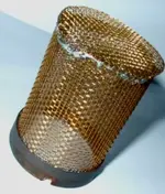
Getting suitable mesh to make the grille was difficult. I tried several different
versions of grille mesh. Finally came up with one that was suitable but a
single layer did not reject mains hum and RF interference well. Had to use
2 layers. The diamond shaped holes in the mesh were probably too big to
get away with a single layer. However,the holes that remain in the two layer version are still sizeably bigger than the holes in the original windscreen mesh.

The reason i'm writing this is not to pat myself on the back but to let anyone
who is interested know the benefits I have noticed from the mod. This may
encourage anyone else who is thinking of giving it a go. But go carefully.

My results agree with what Michaeljoly has already said.

1. The mic seems more 'direct' and 'open'. Slightly 'crisper'.

2. It resolves detail better.

3. One of the 'complaints' I had with the original mic was that it always
seemed too full at the bass end. Low notes and baritone voices sounded
overblown to me.... boomy almost. Using the bass cut switch didnt do
the trick for me somehow.

With the new windshield this problem has almost dissapeared. The mic
is much better balanced. It still sounds big but not boomy. More natural.
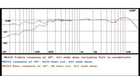
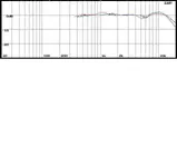
The treble end response of the mic has smoothed out a bit. Little ups and
downs instead of big ones but I can't see this affecting the bass end. Why
the reduction in 'boominess' I dont know. Perhaps I will do a frequency
response plot of the bass end of the mic if I get time. Maybe that will show
up something. To be honest I dont care why, i'm just very pleased.

4. I have done all the mods that have been mentioned in this thread except
playing around with the transistor. This is something I do not understand
so i'm going to keep the original.

5. So is it all worthwhile. Yes, definately in my opinion. Each mod has
improved performance a little and collectively they add up to a distinct
improvement. My MK319 is now the mic I wanted but didn't have before.
Its big, clean, crisp, resolves well, and is evenly balanced.


Once again, thanks everybody.
 
Pic available?

Say Demto,

Any chance you could post of pic of your MK-319 with its new grille? I'd like to see the diamond-shaped screen you used.
 
Michael

I dont have a digital camera. What ive managed to do is lift the lid on my scanner,
put the mic in the scanner and 'scan' it.

The actual picture looks small on the page but if I open Imaging in windows and
locate the jpeg I can then get a bigger image. Its the best I can do and I hope it
comes out OK at your end. Demto
 
Michael
I couldnt attach the image as the file is too big. I dont know much about
computers but I will figure it out. Keep watching. Demto
 
mk 319 mods windshield picture

Michael

Hopefully this time the jpeg will attach.

Resolution is not too good, but best I can do. See my previous posts on this.

Windshield made from 2 seperate circles of steel mesh fitted tightly
together.

Did buy a sheet of finer mesh but it turned out to be made of aluminium.
I was'nt sure it would work plus it dented easily so I decided not to use it.

For the future, do you know if aluminium would be OK as far as RF and
hum rejection are concerned.
 

Attachments

  • MK319 windshield.webp
    MK319 windshield.webp
    10.6 KB · Views: 612
Great MK-319 grille!

Damn Demto, that's a beautiful MK-319 grille.

Did you leave some of the original metalwork in place in order to hold the screen? From the picture it looks like there is some black metal there at the sides of the screen.

That's a very open-looking screen, I'll bet it sounds great.

re: Aluminiun, sure...that's a very conductive material but pretty difficult to solder to. It would be fine for shielding purposes if you could make sure the seams have good closure and are well grounded to the case.

Tomorrow, just for kicks, I'll post a pic of the bronze window screen grille I made for my MK-319 before I decided to turn it into a lollipop-style head.

MJ
 
MK319 mods

Michael

Thanks for your kind words.

There is'nt any supporting metal for the new windscreen, its all mesh.
The picture does have shadows that can look like supports.

The screen is made from 2 tubes of mesh, each with top 'caps'.

One tube is a firm push fit inside the other with butted seams opposite each other. Seams and top caps are tack soldered in about six places.

Fitted to the mic with the original fixing screws plus washers with a flat filed on them.

I 've done a new frequency plot of the mic's response.
The response is now a little flatter than before at the top end.

The blue trace is the mic without the new windshield and the red trace is with new windshield. See jpeg attached.

Your right about soldering aluminium. I got nowhere. Another reason I gave
up on it.
 

Attachments

  • MK319B.webp
    MK319B.webp
    14.3 KB · Views: 534
Demto,

Do you mean the blue trace shows the stock MK-319 windscreen?

The new response is really smooth at the top. Just a touch of HF boost, a good mic for digital recording.

Attached is my first attempt to roll a new MK-319 screen. This one is a single rectangle of bronze window screen rolled twice to form a double layer cylinder. There's a copper band at the bottom to which the screen is soldered. The copper band attaches to the mic body with the original screws. The day I did this I only had a low-wattage soldering iron so the solder flow was not too good. Flux and high heat is needed for this work.
 

Attachments

  • mk319test1.webp
    mk319test1.webp
    23.3 KB · Views: 660
MichaelJoly said:
Demto,

Do you mean the blue trace shows the stock MK-319 windscreen?

The new response is really smooth at the top. Just a touch of HF boost, a good mic for digital recording.

Attached is my first attempt to roll a new MK-319 screen. This one is a single rectangle of bronze window screen rolled twice to form a double layer cylinder. There's a copper band at the bottom to which the screen is soldered. The copper band attaches to the mic body with the original screws. The day I did this I only had a low-wattage soldering iron so the solder flow was not too good. Flux and high heat is needed for this work.
Michael

The blue trace is the mic after all the previous mods, boost discs removed, body
dampened and electronics updated etc.

The red trace shows what difference the new headshell makes in the response when compared to this.

I know i'me a pest but do you happen to know if there is an alternative to the original transistor [mines a 76F7] that would sound better. If so do any other components need changing to make it work.
 
FET alternative

The 2SK170 FET has been used as a replacement. That and the swapping 1G Ohm resistors for the 680 Ohm resisters are the heart of the "Dorsey Mod" for the MK-012 that can be used on the '219/'319. A search on Google groups for "Oktava 2sk170" will bring up a couple of threads.

I've done this swap but, but at least on the mics I've done it to, the improvements are so subtle, if any, in comparison to the mechanical mods and signal path capacitor changes that I no longer change the FET or resistors.

The 2SK170 does have a couple of dB lower noise than the stock unit if that's important to you. If you do the swap, make sure you have some PC board cleaning solvent on hand to thoroughly deflux the board after the change.
 
Michael

I've already done all the other mods/upgrades, and if you don't change the transistor then I won't. Your word is good enough for me and thanks for your help.
 
I tried several 2SK170BL's in mine and they all sounded thinner to me. I ended up leaving the stock FET in there - sounds fuller and more musical in MHO. Now that you mention it, I thought it sounded better with the original resistors in it too. I know it doesn't make sense (Believe me I know it doesn't since this greatly improved ever other mic I modified! :confused: ) but that's what I found. I haven't had time to measure anything, but my guess is that these changes mess up the way the FET is biased.

Referring to the schematic I posted a link to on page one, I'd just change C2 to a 1000pF polystyrene and C8 to a high quality 1uF or larger metal film.
 
Back
Top