M
Minion
Blow Me !!!
Hi, I simply just use ExpressPCB to design the PCB and then use a couple Graphics programs to draw out the actual curcuit board, It is a Bit tedius but It is the only way i know how to do it...
Yes , I can share the design....
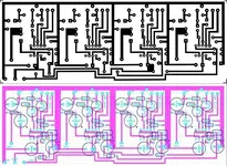
Here is my 4ch version....
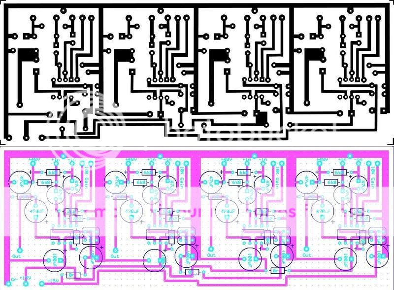
The Values for each Channel are the same and each channel is Identicle so you should be able to figure out the values from looking at the Parts overlay, I haven"t done the Offboard connections yet but you should be able to figure it out at the Phantom power is labeled, and the +in/-In are labeled and the Output is labeled...I suggest that you run the Input/Output grounds right back to a star ground or back to 0v Power ground as opposed to useing the Ground plane on the Board......
I also have PCB designs for Regulated PSU"s that also put out 48v Phantom if you are interested.....
any questions?? Just ask....
Yes , I can share the design....
Here is my 4ch version....
The Values for each Channel are the same and each channel is Identicle so you should be able to figure out the values from looking at the Parts overlay, I haven"t done the Offboard connections yet but you should be able to figure it out at the Phantom power is labeled, and the +in/-In are labeled and the Output is labeled...I suggest that you run the Input/Output grounds right back to a star ground or back to 0v Power ground as opposed to useing the Ground plane on the Board......
I also have PCB designs for Regulated PSU"s that also put out 48v Phantom if you are interested.....
any questions?? Just ask....
Last edited:
 I'll have to print it at work, though.
")